Xylem 795 MJK Data Transmitter User Manual
Page 9
9
M795GB0503
Data Transmitter 795
SW ver. 830434
3
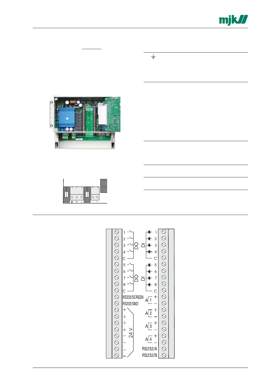
Electrical mounting
Data Transmitter 795 must not be mounted in
explosion hazardous areas!
Data Transmitter 795 must not be connected to
the power supply before all connections are
made.
Remove the terminal lid and the front panel to
gain acces to all terminals.
3.1
Power supply
Data Transmitter 795 can be supplied from both
230 V AC and 24 V DC.
Terminal:
Designation:
Protective ground
N
230 V AC neutral
L
230 V AC live
-
24 V DC negative
+
24 V DC positive
Please note, that 24 V DC will not be available on
the terminals marked '24 V DC forsyning' unless
the Data Transmitter is fed from the mains.
3.2
In- and output signals
Data Transmitter 795 is delivered in 3 different I/O
variants; 4AI / 8DI / 8DO, 4AI / 12DI / 4DO and
4AI / 16DI respectively.
Specifications:
DI:
Passive with common negative, max. 24 V DC.
(Optocoupler med 10 k
Ω
serial resistor)
Trig voltage: < 1 V DC = Off, > 10 V DC = On,
pulse length > 100 ms.
DO: Voltage free relay contacts,
max. 1 A @ 24 V DC / 0,5 A @ 48 V AC.
AI:
0/4 - 20 mA or 0 - 1 V DC.
Input impedance = 50
Ω.
DI 1 +
DI 2 +
DI 3 +
DI 4 +
DI 1/2/3/4 common -
DI 5 +
DI 6 +
DI 7 +
DI 8 +
DI 5/6/7/8 common -
AI 1 +
AI 1 -
AI 2 +
AI 2 -
AI 3 +
AI 3 -
AI 4 +
AI 4 -
Rx for RS232 to 704
Tx for RS232 to 704
DO 1
DO 2
DO 3
DO 4
DO 1/2/3/4 common -
DO 5
DO 6
DO 7
DO 8
DO 5/6/7/8 common -
Shield for RS232 to 704
Signal ground for RS232 to 704
24 V DC out +
24 V DC out -
3.2.1 I/O terminals, 8 DI/8 DO/4 AI