Xylem 795 MJK Data Transmitter User Manual
Page 14
14
M795GB0503
Data Transmitter 795
SW ver. 830434
5
Functional menus
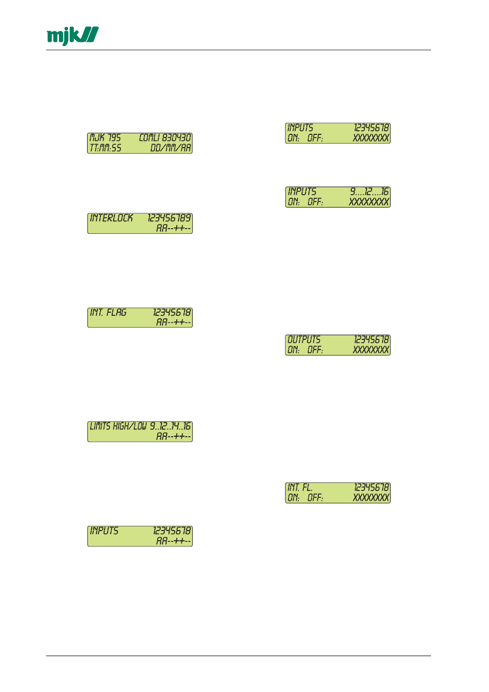
5.1.1 F0 - Program version, time and date
Menu F0 displays date og and time. Moreover, it
will display the current communications protocol
and program version.
5.1.2 F0 - Interlock, operation or alarm signal
Menu F0 followed by 1 x 'down arrow' will display
which signals that initiate the 9 programmable in-
terlock sequences:
'A': alarm signal, '+': operation signal,
'-': not in use.
5.1.3 F0 - Internal flag, operation or alarm signal
Menu F0 followed by 2 x 'down arrow' will display
which signals that are linked to the internal flags:
'A': alarm signal, '+': operation signal, '-':
not in use.
5.1.4 F0 - Limits, high/low
Menu F0 followed by 2 x 'down arrow' will
indicate which analogue inputs that are linked to
a high/low alarm limit, and also if the limit will
release an operational or alarm signal:
'A': alarm signal, '+': operation signal, '-':
not in use.
5.1.5 F0 - Digital inputs, operation or alarm signal
Menu F0 followed by 4 (and 5) x 'down arrow'
display which digital inputs, that releases an ope-
ration or alarm signal:
'A': alarm signal, '+': operation signal, '-':
not in use.
5.2
F1 - Digital inputs on/off
Menu F1 indicates if the digital inputs are set ON
or OFF. Up to 8 inputs are shown simultaneously.
If there are more than 8 inputs, the remaining
inputs will be displayed by pressing one of the
arrow keys:
Note, that a delay period can be set for every di-
gital input so that the digital input can go ON for a
short period without triggering an eventual alarm.
When the input is OFF, an empty field is
shown. When the input goes ON, a flashing field
is shown during the delay time, after which a field
is shown constantly.
5.3.1 F2 - Digital outputs on/off
Menu F2 displays whether the digital outputs are
set ON or OFF:
A delay period can be set for every digital output.
This delay period must run out before the output
are activated.
When the output is OFF, an empty field is
shown. When the output goes ON, a flashing field
are shown during the delay time, after which a
field are shown constantly.
5.3.2 F2 - Internal flag on/off
Menu F2 followed by 1 x 'down arrow' will display
the status for the internal flags.