Xylem 795 MJK Data Transmitter User Manual
Page 21
21
M795GB0503
Data Transmitter 795
SW ver. 830434
9
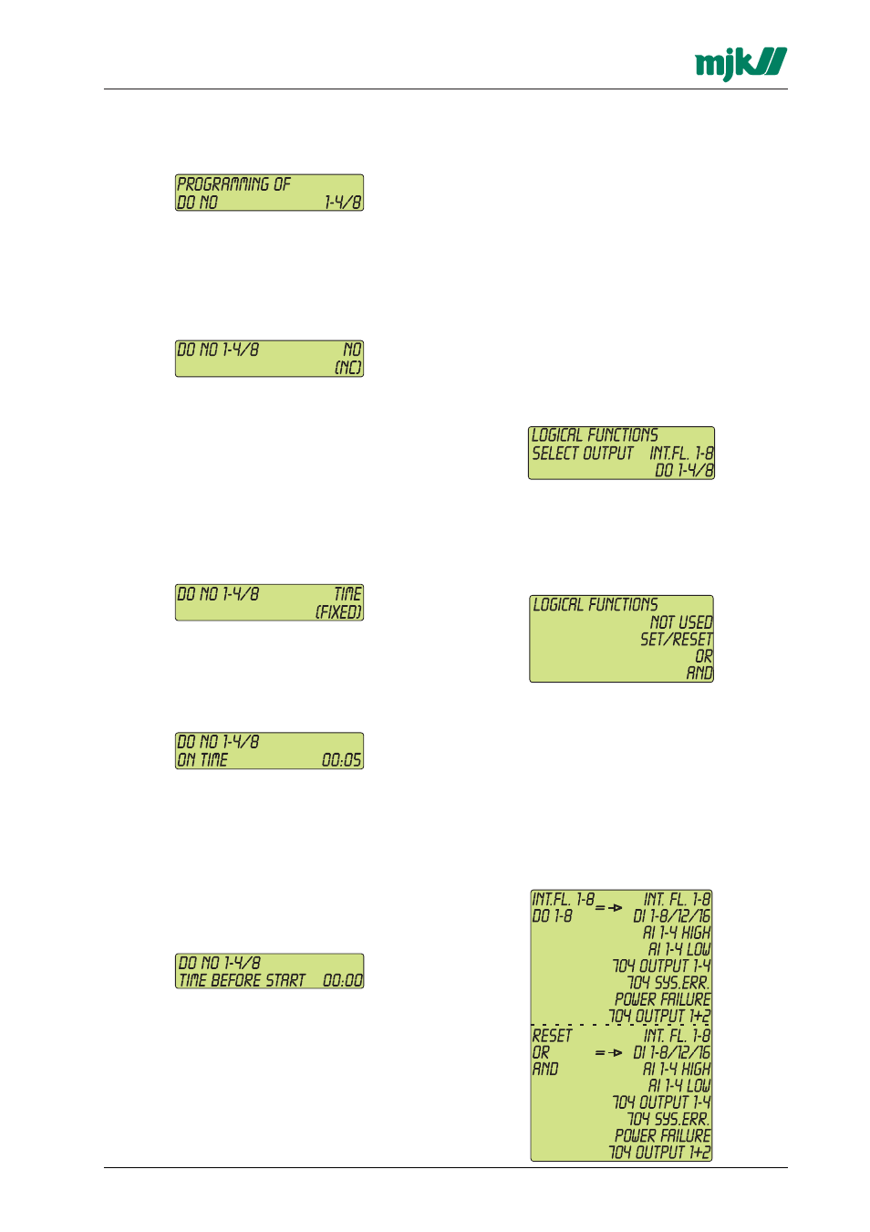
Programming of digital outputs
9.1
Select a digital output
Select the desired digital output with the arrow
keys and confirm with ENTER.
9.2
NO or NC
Select if the relay contact should be open (NO) or
closed (NC), when the output is not active.
Use the arrow keys and confirm with ENTER.
9.3
Time controlled output
Select if the output should go ON and stay ON
when the Data Transmitter receive a start signal
('FIXED'), or if the output should go ON when the
Data Transmitter receive a start signal and stay
ON for a pre-set period of time ('TIME').
If 'FIXED' are selected, the Data Transmitter need
a stop signal in order to deactivate the output.
Use the arrow keys and confirm with ENTER.
9.4
ON time
Select the period in which the output should be
active, if the output is set to be 'TIME' controlled.
Use the arrow keys (double arrow for minutes
and single arrow for seconds) and confirm with
ENTER.
9.4.1 Time before start
Select the delay time for activation of the output
relay. The delay time is from the moment the Data
Transmitter receive an ON command and until the
relay output will be activated.
Use the arrow keys (double arrow for minutes
and single arrow for seconds) and confirm with
ENTER.
10
Programming of logical functions
This menu gives the possibility to program simple
logical functions like AND, OR, and SET/RESET
based on different digital signals in both Data
Transmitter 795 and the Pump Controller 704 (if
connected).
Since it is also possible to set internal flags in
Data Transmitter 795, it will be possible to make
combina-tions of several logical function and thus
obtain PLC-like logical functions in the Data Trans-
mitter 795.
10.1 Select the output to receive the result of
the logical function
The result of a logical function can be sent to an
internal flag or directly to a digital output.
Select the desired signal with the arrow keys and
confirm with ENTER.
10.2 Select logical function
Select the desired logical function for the signal.
Use the arrow keys and confirm with ENTER.
10.2.1 Select signals for the logical function
Select the signals to be used for the logical function.
In the left hand side of the display is shown the
previous selected signal type to receive the result
of the logical function together with the selected
logical function.
In the right hand side of the display is shown the
input signals for the selected logical function.