Xylem 795 MJK Data Transmitter User Manual
Page 11
11
M795GB0503
Data Transmitter 795
SW ver. 830434
3.3
Connection examples
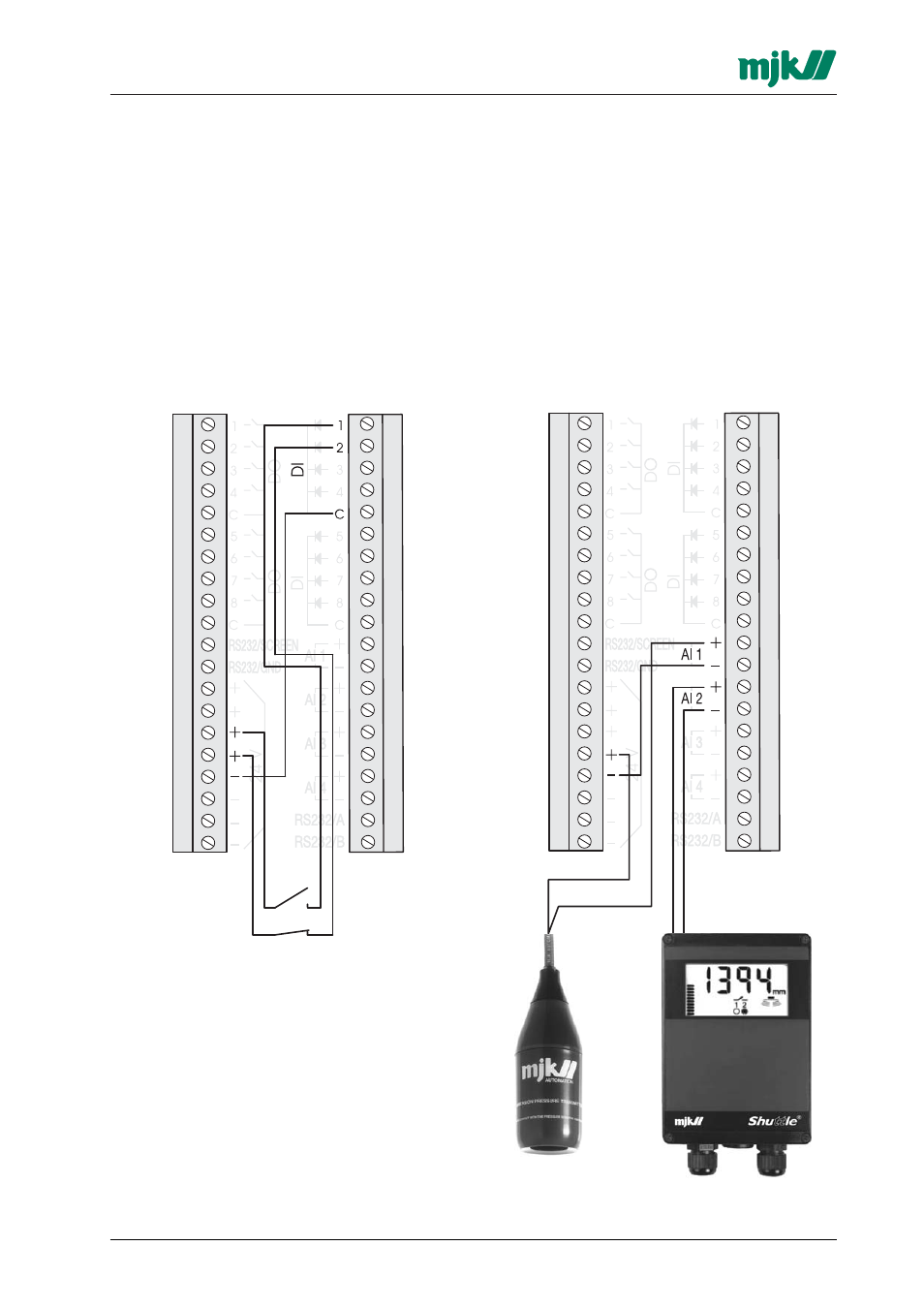
3.3.1 Digital inputs
The digital inputs are passive, i.e. they need to be
supplied from an external power source or from
the terminals marked '24 V'.
Note, that the inputs has common negative in
groups of 4 inputs.
A common installation error is that an input is
not connected to the correct negative terminal!
The inputs can be individually configured to be
normally open (NO) or normally closed (NC).
Above diagram show an example of connecting two
switches to DI1 and DI2. Note the common
negative terminal!
3.3.2 Digital outputs
The digital outputs are voltage-free relay contacts
with a capacity of max. 24 V DC / 1 A or max. 48
V AC / 0,5 A resistive load.
The outputs can be individually configured to be
normally open (NO) or normally closed (NC).
3.3.3 Analogue inputs
The analog inputs are passive. i.e. they must be
supplied from an external power source or from
the terminals marked '24 V'.
Every input have its own plus and negative termi-
nal.
A common installation fault is that an input is
not connected to the correct negative terminal!
The input range can be individually configured to
0-20 mA or 4-20 mA.
A passive mA signal
from a pressure
transmitter.
An active mA signal from
a level transmitter.