Armasight NAM601500126DH1 PVS14/6015 GEN 2+ HD Multi-Purpose Night Vision Monocular User Manual
Page 40
40
CAUTION
:
• To prevent damage, do not use excessive force when changing the up/ down position of the
MUNVM.
• Do not drop or throw the helmet with the helmet mount attached to it.
• If the monocular is flipped up, do not flick the monocular down by shaking the helmet. This
places significant stress on the helmet mount.
• All Other Services – Return the helmet and the helmet mount to unit maintenance to have the
bracket directly mounted via the helmet screws.
NOTE
:
The headmount/ helmet mount adapter allows the MUNVM to be rotated from the left to the
right eye or vice versa. The MUNVM can be flipped up with the headmount/ helmet mount
adapter positioned over either eye
NOTE
:
The helmet mount allows the user to position the MUNVM in two ways: flipped up or flipped
down. When flipped down, the device is directly in front of the eyes. When flipped up, the unit
remains out of the line of sight. Both positions have a positive stopping point to indicate that
the device is positioned correctly.
Perform the following for helmet-mounted operation.
(1) Verify that the batteries are installed per paragraph 3.3.2.
(2) Put the helmet mount on per the instructions in paragraph 3.3.8.
(3) Place the monocular in the socket of the helmet mount.
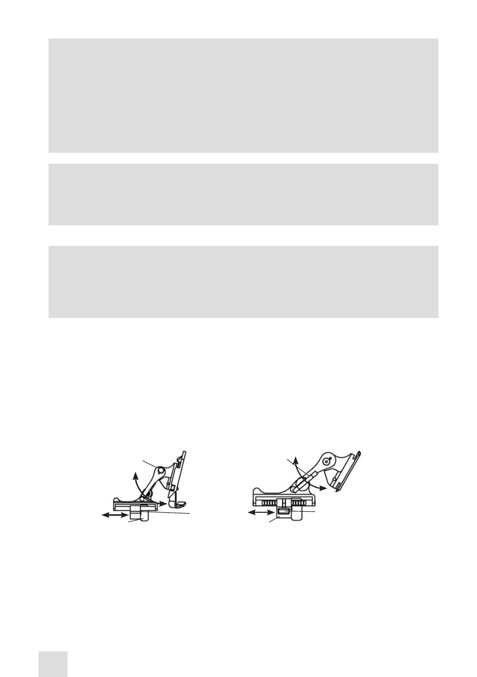
Set your eye relief by depressing the side buttons (or, if using a metal mount, the side lever) (see Figure
3-24) and carefully move the monocular fore or aft until the eyecup comfortably seals around the eye.
Readjust the helmet straps as required for vertical adjustment.
(4) Turn to the device ON. Adjust the tilt using the tilt adjustment lock knob, or tilt adjustment lever on
the metal mount (Figure 3-24), until you obtain a comfortable viewing angle.
PLASTIC MOUNT
TILT ADJUSTMENT
LOCK KNOB
SOCKET
SIDE
BUTTONS (2 EA)
(FORE-AND-AFT
ADJUSTMENT)
METAL MOUNT
TILT ADJUSTMENT
LEVER
SOCKET
SIDE LEVER
(FORE-AND-AFT
ADJUSTMENT)
Figure 3-24. Tilt and Flip-up Assembly Mechanisms