2 controls and indicators, 1 co-mini controls and indicators – Armasight NSCCOMINI139DA1 CO-Mini GEN 3+ Alpha MG Night Vision Mini Clip-On System User Manual
Page 25
25
3.2 CONTROLS AND INDICATORS
CAUTION:
DO NOT force the equipment controls past their stopping points.
3.2.1 CO-MINI CONTROLS AND INDICATORS
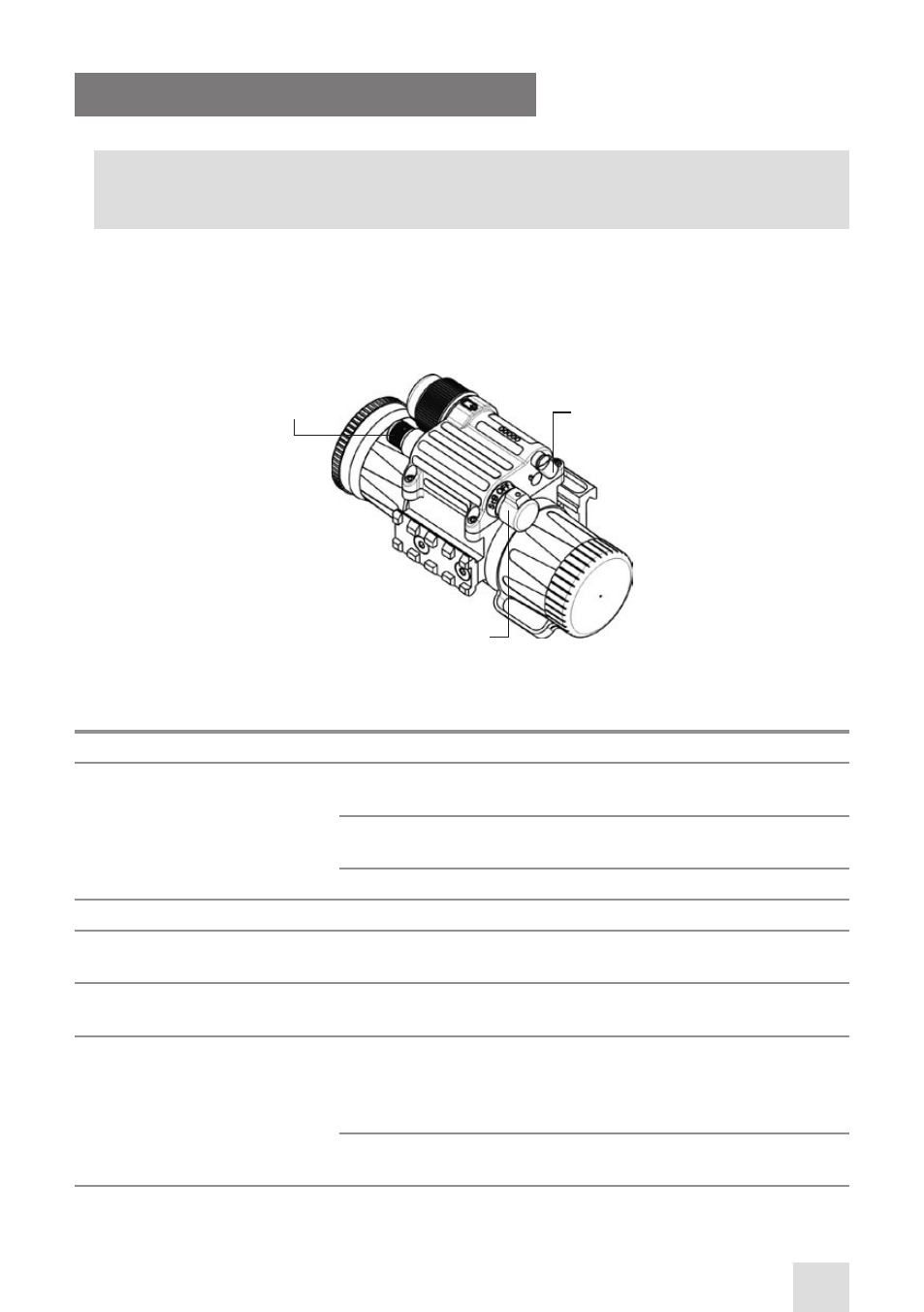
The CO-MINI controls are shown in Figure 3-14.
The CO-MINI controls and indicators are defined in Table 3-1. The ITEM NO. column indicates the num-
ber used to identify items in Figure 3-14.
TABLE 3-1. CO-MINI CONTROLS AND INDICATORS
ITEM NO.
CONTROL/INDICATOR
FUNCTION
1
Turn-push Switch
Activates the CO-MINI when turned CW from OFF to ON. The
switch must be pushed to turn the device on.
Activates the standby mode when turned CCW from OFF to STB.
The switch must be pushed to switch to STB.
Deactivates the CO-MINI when turned from ON/ STB to OFF.
2
Gain Control Knob*
Adjusts the brightness of the image.
—
Remote Control Button
Activates/deactivates the CO-MINI in standby when pressed/
released.
3
Pivoted Shutter
Closes/opens the photoreceiver when placed in the highest/low-
est position.
—
Built-in Bi-color LED
Indicator
PERMANENT YELLOW GLOW in the viewing area indicates exces-
sive light conditions. After 10 seconds of exposure to excess light,
the image intensifier tube will be cut off. The CO-MINI will turn
back on when moved away from the excessive light.
A FLASHING RED LIGHT in the viewing area indicates a low bat-
tery. The LED will flash three times every 3 minutes.
* For CO-Mini MG version only.
FIGURE 3-14. CO-MINI CONTROLS
3
1
2
- NSCCOMINI1P9DA1 CO-Mini GEN 3P MG Night Vision Mini Clip-On System NSCCOMINI1G9DA1 CO-Mini GEN 3 Ghost MG Day/night vision Clip-On system Standart Definition NSCCOMINI1F9DA1 CO-Mini Flag MG Day/night vision Clip-On system Standart Definition NSCCOMINI139DB1 CO-Mini GEN 3 Bravo MG Night Vision Mini Clip-On System NSCCOMINI129DI1 CO-Mini GEN 2+ ID MG Day/night vision Clip-On system Improved Definition NSCCOMINI129DH1 CO-Mini GEN 2+ HD MG Day/night vision Clip-On system NSCCOMINI1Q9DI1 CO-Mini GEN 2+ QS MG Day/night vision Clip-On system