4 clamping device adjustment – Armasight NSCCOMINI139DA1 CO-Mini GEN 3+ Alpha MG Night Vision Mini Clip-On System User Manual
Page 21
21
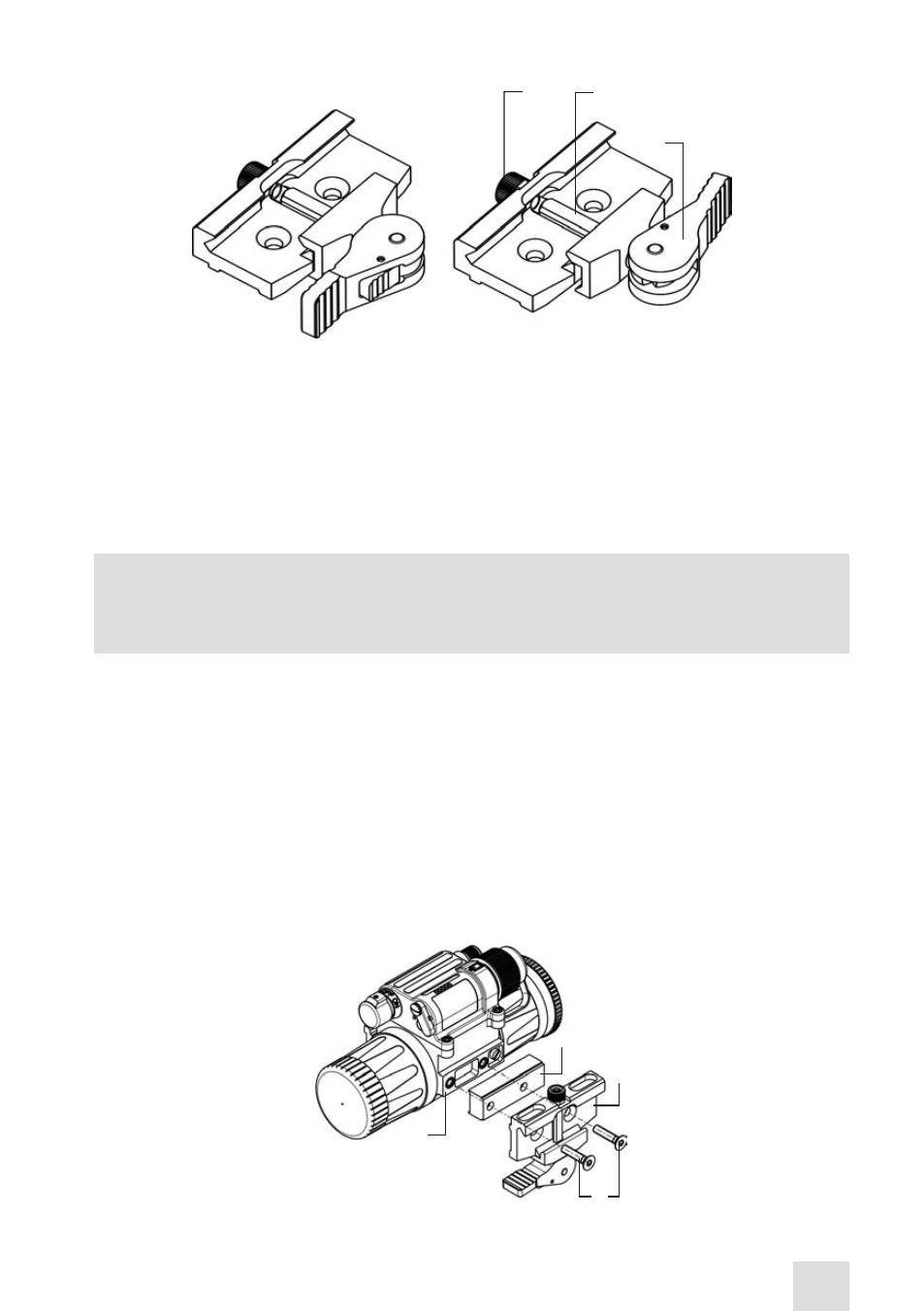
3.1.4 CLAMPING DEVICE ADjUSTMENT
Adjust the mount clamping device as follows (refer to Figure 3-6):
1. Unlock the clamping device and remove the CO-MINI from the weapon.
2. To tighten or loosen the clamping device, push the cam (C) towards the arrow. This will cause the nut
(A) to slide out of the hollow. Turn the nut (A) CW/CCW respectively, in one-two increments (see note
below). Much like when the cam (C) is released, the backward-moving springs in this mechanism will
cause the nut (A) to slide back into the hollow.
NOTE
:
The eight-sided nut of the clamping device will only fit into the hollow if turned in one of the
discrete positions using increments equal to 360°/8.
3. Verify that the adjusted clamping device firmly holds the CO-MINI.
3.1.5 MOUNTING THE CO-MINI IN FRONT OF AN ACOG 4×32 SCOPE
When mounting the CO-MINI in front of an ACOG 4×32 scope, use the optional raiser and light sup-
pressor ACOG.
To mount the CO-MINI to a Picatinny/ Weaver rail in front of an ACOG 4×32, do the following (refer to
Figure 3-7):
1. Using a 2.5mm Allen key, unscrew both of the М4×8 fixing screws of the CO-MINI mount. Remove the
device from the seating rail.
2. Apply a small amount of thread lock to the threads. Secure the raiser (A), together with the mount (B),
to the seating rail (D) with two furnished М4×18 screws (C). Use a 2mm Allen key.
A
B
C
d
FIGURE 3-7. INSTALLING THE MOUNT WITH THE RAISER
FIGURE 3-6. MOUNT. UNDERSIDE VIEW
A
B
C
UNLOCK
POSITION
LOCKEd
POSITION
- NSCCOMINI1P9DA1 CO-Mini GEN 3P MG Night Vision Mini Clip-On System NSCCOMINI1G9DA1 CO-Mini GEN 3 Ghost MG Day/night vision Clip-On system Standart Definition NSCCOMINI1F9DA1 CO-Mini Flag MG Day/night vision Clip-On system Standart Definition NSCCOMINI139DB1 CO-Mini GEN 3 Bravo MG Night Vision Mini Clip-On System NSCCOMINI129DI1 CO-Mini GEN 2+ ID MG Day/night vision Clip-On system Improved Definition NSCCOMINI129DH1 CO-Mini GEN 2+ HD MG Day/night vision Clip-On system NSCCOMINI1Q9DI1 CO-Mini GEN 2+ QS MG Day/night vision Clip-On system