GE Industrial Solutions 6KCV300lNS User Manual
Page 6
GEI-100445
2.3
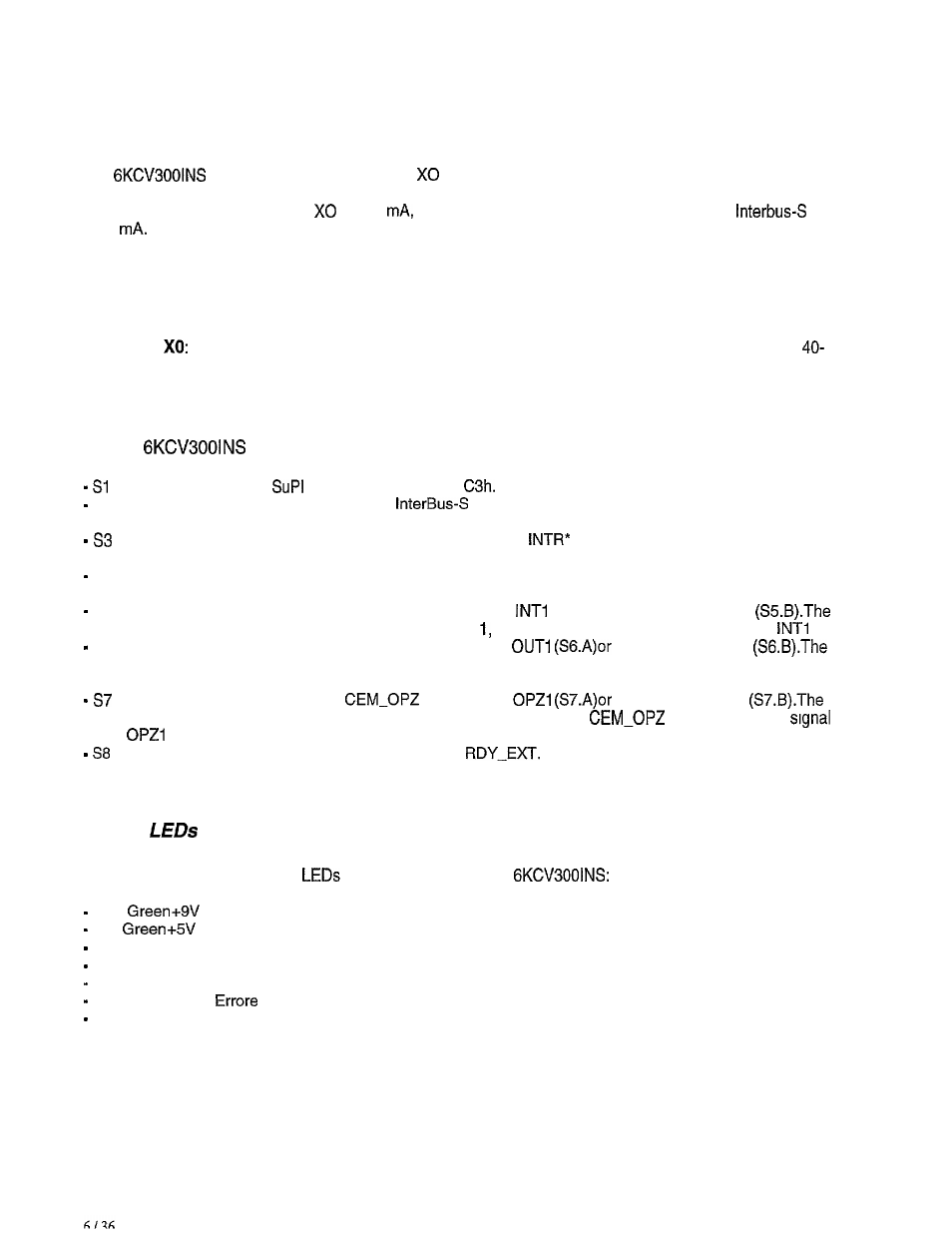
Power Supply
The
card are supplied through the
connector which links them to the drive regulation card
and through the local Bus line InterBus-S There is no need to supply the card from the outside.
The current draw of the connector
is 350
while the current drawn from the local Bus line
is 70
2.4 Connectors
Connector
It allows to connect directly the InterBus-S interface card to the regulation card; it is
pin connector.
2.5 Switches
On the
card there
are the following Switches:
s2
s4
s5
S6
Configuration Switch
II, their value must be
It is used to connect the shield of the
connection cables to the GND supply reference. It
has a default connection.
It is used to connect the signal INT-OPZ to the signal
(S3.A) or to the port P1.4 of CPU
(S3.B). Default S3.B.
It is used to connect the reset of the regulation card TRST to the reset circuit of the interface. It is
inserted by default.
It is used to connect the signal INT-OPZ to the signal
(S5.A) or to the signal INT2
interface card is configured per default as OPTION therefore INT-OPZ is linked to the signal
.
It is used to connect the signal OUT-OPZ to the signal
to the signal OUT2
interface card is configured per default as OPTION 1, therefore OUT-OPZ
IS
linked to the signal
OUT1 .
It is used to connect the signal
to the signal
to the signal OPZ2
interface card is configured per default as OPTION 1, thereforei
is linked to the
.
It is used to connect the signal BSY to the signal
It is inserted by default.
2 . 6
A series of diagnostic and state
are present on the cards
HO
(Line Power Supply).
Hi
(Regulation Power Supply).
H2 Red
Reset.
H3 Yellow
Communication (LBDA).
H4 Red
Disable the Extended RB Interface (RBDA).
H5 Red
(Error).
H6 Green
Active lnterbus (BA).