Output, Process data from interbus-s, Pdc output channel – GE Industrial Solutions 6KCV300lNS User Manual
Page 15: Pdc output data, Parameter 2, P.l*p.l*p.l*p.l*p.2*p.2*p.2*p.2, Pdc input data . . . . . . . . . ***descriptor
-S
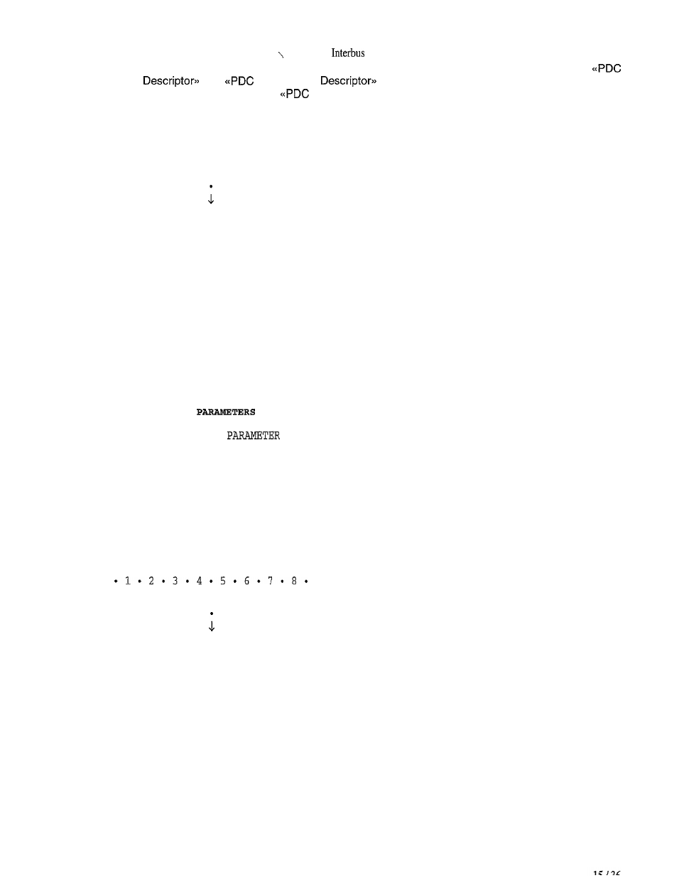
The assignment of the processed data to specific drive parameters can be set. To this purpose the
Input data
and
Output
data
communication objects are involved . The output
data can be enabled or disabled by the
output Enable= communication object .
How it works:
Process Data from Interbus-S
.
.................................
l
1 = 2 * 3 * 4 * 5 * 6 * 7 * 8 *
PDC Output Channel
.................................
.
.
.
.
.
.
.
.
.................................
l
1 * 2 * 3 * 4 * 5 * 6 * 7 * 8 *
PDC Output Memory
.......................................................
.
.
.
.
.
.
.
.
.
PDC Output
.
. . . . . . . . . . . . . . . . . . . . . . . .
* * * E n a b l e
.
..............................................
. . . . . . . . . . . . . . . . . . . . . . . . . . . . . .
. . . . . . . . .
**PDC Output data
.
.
.
.
.
.
.
.
.
- d e s c r i p t o r
.
.......................................................
l
P.l*P.l*P.l*P.l=P.2*P.2*P.2*P.2*
.................................
.
PARAMETER 1
l
PARAMETER 2
l
. . . . . . . . . . . . . . . . . . . . . . . . . . . . . . . . .
.
DRIVE
.
.................................
.
PARAMETER 1
l
2
l
. . . . . . . . . . . . . . . . . . . . . . . . . . . . . . . . .
l
P.l*P.l*P.l*P.l*P.2*P.2*P.2*P.2*
.................................
.
.
.
.
.
.
.
.
.
.
.
.
.
.
.
.
.
.
.
.
.
.
.
.
.
.
.
.
.
.
.
.
.
.
.
.
.
.
.
PDC Input data
.
.
.
.
.
.
.
.
.
***descriptor
.
.
.
.
.
.
.
.
.
.
.
.
.
.
.
.
.
.
.
.
.
.
.
.
.
.
.
.
.
.
.
. . . . . . . . . . . . . . . . . . . . . . . . . . . . . . . . .
l
1 * 2 * 3 * 4 * 5 * 6 * 7 * & *
PDC Input Memory
.................................
.
.
.
.
.
.
.
.
. . . . . . . . . . . . . . . . . . . . . . . . . . . . . . . . .
PDC Input Channel
.................................
.
Process Data for Interbus-S