Programming the meter – GE Industrial Solutions BDCBB H569-445 User Manual
Page 25
Secondary DC Power Distribution Bay H569-445
Issue 3 June 2012
25
Programming the Meter
VIM1C parameters like shunt size and number of load buses are preconfigured when it is factory
installed in a BDFB. Only customer specific preferences need to be adjusted in the field. As a
replacement or meter upgrade, the factory default settings may need to be adjusted for the
application. Listed below are the configurable parameters and their associated factory defaults
available through the front panel. Following the table are the typical items that need to be
configured or verified in a retrofit or replacement application.
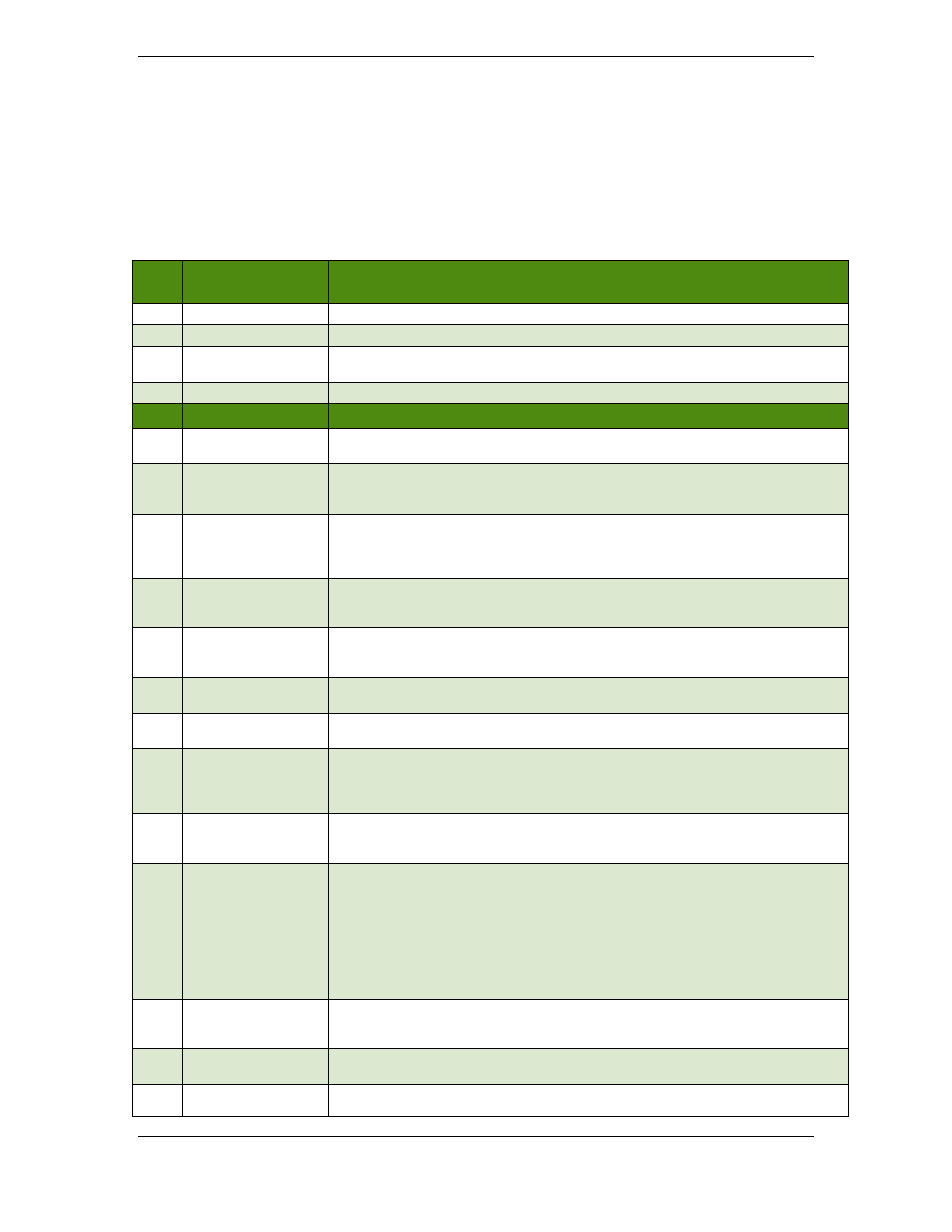
Item
System
Parameters
Description
1
System Voltage
Factory default is 48V.
2
Local Buzzer
Allows audible alarm to be Enabled or Disabled. Factory default is Disabled.
3
Display Contrast
Allows the display contrast to be adjusted for the local ambient lighting. Adjustable from 0-
100% in 1% increments. Factory default is 50%.
4
Software Version
Displays the version of the application code running in the meter.
Load Parameters
Description
5
Number Of Loads
Used to identify the number of individual loads/buses in the BDFB. Factory set from 1-8
depending on BDFB configuration.
6
Meter Type
Configures meter to display individual monitored bus voltages (voltage), voltages and
currents (volt_curr), or only currents (current). Factory default is Voltage and Current
(volt_curr).
7
Load ID Format
Configures display format used in referencing individual DC loads/buses. Allowable
formats: A1, A, and 1. “A1” identifies loads using an A1, B1; A2, B2; … format. “A”
identifies loads using an A, B, C, D ... format. “1” identifies loads using a 1, 2, 3, 4 …
format. Factor Default is A format.
8
First Load (location)
Used to indicate where the first load in the distribution is located. Allowable configurations
are: top-left, top-right, btm-left (bottom-left), btm-right (bottom-right). Every monitored shunt
is considered a load. Factory default is determined by BDFB configuration.
9
Shunt Rating
Used to define the current rating of the shunt in the load bus. All shunts in the load must be
of the same size. A 50mV shunt is assumed. Allowable range is 1-4000A. The factory
default is 1500A in the BDFB.
10
Overload Latch
A single configuration for all panels/buses that allows a temporary Over Load event to be
latched. Factory default is “Disabled”.
11
Combined Load
Displays the load value as one combined sum by adding up all shunts in the system and
presenting it as values for a single load. Factory default is disabled.
12
Load Available
Indicates if the load is available or in use. Allowable configurations are “installed” and “not
installed”. “Installed” loads imply that the load is in use. “Not Installed” loads imply that the
load may be present, but it is not in use. Information obtained from the load should not be
relevant. Factor default is set to be “installed”.
13
Load Power Loss
The Power Loss (PL) alarm is triggered upon loss of the primary DC or when the
individual’s panels’ DC input has reached the configured low voltage threshold. This Power
Loss voltage threshold is configurable between 40.00-60.00V. Factory default is 40.00V.
14
Load Overload Type
The Power Overload Type defines whether the smart meter is to treat the Overload alarm
event for a “Single Bus” or for a “Redundant Bus” configuration. The “Single Bus”
configuration is based on straight Overload threshold being exceeded. The “Redundant
Bus” configuration causes the VIM1 to sum the two respective left and right load shunt
measurements and compare it to the individual overload thresholds configured for the each
of the respective panels in the pairing. The lowest Overload value threshold configured for
the Redundant loads shall take priority and be used in the comparison. Once the
“Redundant Bus” measurement exceeds this threshold, the controller asserts the Over
Load (OVL) alarm. Factor default is “Single Bus” configuration”.
15
Load Overload
The Load Overload (OVL) alarm event is triggered when any measured panel currents
exceed their respective configured thresholds. These OVL thresholds can be configured
from 1-4000A. Factory default is 800A.
16
Load Overload Delay
An Overload Delay can be set to prevent nuisance alarms. This delay is configurable
between 0-300 seconds. Factory default is 0 seconds.
17
Assigned Circuits
The VIM1 has eight individual load circuits with each circuit having voltage and shunt
measurement capability. These circuits are pre-wired with fixed positions in the BDFB. If