Load bus arrangements – GE Industrial Solutions BDCBB H569-445 User Manual
Page 19
Secondary DC Power Distribution Bay H569-445
Issue 3 June 2012
19
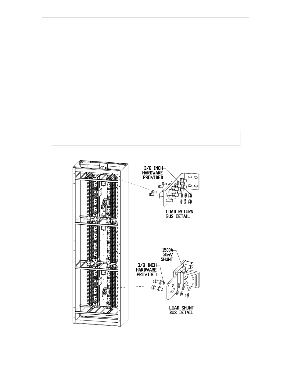
Load Bus Arrangements
A load bus is defined as one or more panels protected by a single circuit breaker or fuse
at the battery plant. Cable from the battery plant is terminated at Load Shunt Bus
Details rated for 800 amperes. (Two 750 kcmil feeder cables are required per shunt for
currents larger than 500 amps per shunt.) 3/8 inch hardware is provided for this
connection. The cabinet may be equipped for 2, 4 or 6 loads. In 2 or 4 load
configurations a bus bar link connects some panels together vertically. The 800 ampere
capacity per load bus applies even if multiple fuse panels are connected together.
When internal return buses are ordered, load return bus details will be located either at
the top or the bottom of the cabinet as shown depending on if a top cable feed or
bottom cable feed was ordered. These may easily be unbolted and moved if the
application requires. 3/8 inch hardware is provided for load return cables.
Note
All bus bars are copper with a bright tin finish. Bus bars do not require buffing or
the application of NO-OX before connection to terminal lugs or other bus bars.
Figure 10 Load Connection Points