6 epo (emergency power off) input contact, Epo (emergency power off) input contact, Terminals xb – GE Industrial Solutions SG Series 750 T12 UL S2 Installation Guide User Manual
Page 48
Modifications reserved
Page 48/49
OPM_SGS_ISG_M75_M75_2US_V010.doc
Installation Guide SG Series 750 UL S2 & SG Series 750 T12 UL S2
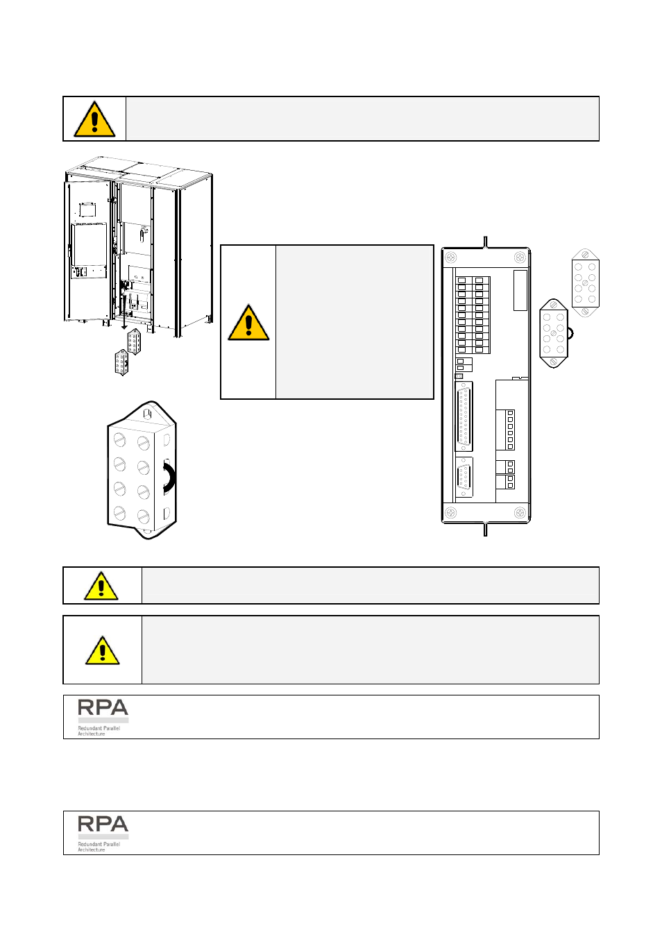
4.1.6 EPO (Emergency Power Off) Input contact
BE AWARE !
The reliability of the system depends on this contact NC (Normally Closed)!
An external Emergency switch (Normally Closed voltage-free contact)
can be connected on terminals XB / 1 - 4 or connector J2 / 12 - 25 of the
P4 - Interface Customer.
NOTE !
To enable this function,
remove cable short-
circuiting XB / 2 - 3 on the
Terminal XB and the
Jumper JP3 on P4 –
Customer Interface, when
the cables have been
already connected on XB
or J2.
SGS_750_S2_
UPS_XA-XB_01
Q1
XB
XA
1
2
3
4
4
3
2
1
2
3
1
4
2
3
1
4
2
1415
34
16
1
7
56
19
20
89
18
7
22
11
1
21
10
12
12
13
Terminals XB
SG
S
_75
0_
T
e
rm
in
al
s XA
_0
1
2
4
3
1
Fig. 4.1.6-1 Terminals XB for connection EPO
When opened, this contact causes the
immediate opening of the Bypass
Contactors K6 and K7, Rectifier input
contactor K4, External Battery Breaker (if
present) as well as the shutdown of the
Rectifier and the Inverter and the Static-
Switch.
1
12
13
2
14
3
15
4
16
5
17
6
18
7
19
8
20
9
21
10
22
11
1
14
9
1
J2
S
G
S
_750_Cus
to
mer
in
te
rf
ace_J2
-JP
3_01
2
1
JP3
1
1
2
2
3
3
4
4
XB
41
32
41
32
3
2
1
3
2
1
2
11
2
Fig. 4.1.6-2 Customer interface
NOTE !
This procedure could imply a Load shutdown.
NOTE !
In case of parallel Customer Interface the EPO contact must be connected to one
Customer Interface only, but the bridge on X2 and Jumper JP3 on the P4 –
Customer Interface must be removed on all other boards.
In a parallel system a separate NC (Normally Closed) contact must be connected
individually to each unit.
When the EPO has been activated, the system must be restored as follows:
•
Realize the push-button EPO (contact on XB / 1, 4 is closed again).
•
Press the key “O” (Inverter Off – see Section 5.2 – Operating Manual) on the control panel.
In case of a parallel system press the key “O” (inverter Off) on the control panel of
each unit connected on the parallel bus and having its output switch Q1 closed.