2 power connection with common input utility, Power connection with common input utility – GE Industrial Solutions SG Series 750 T12 UL S2 Installation Guide User Manual
Page 31
Modifications reserved
Page 31/49
OPM_SGS_ISG_M75_M75_2US_V010.doc
Installation Guide SG Series 750 UL S2 & SG Series 750 T12 UL S2
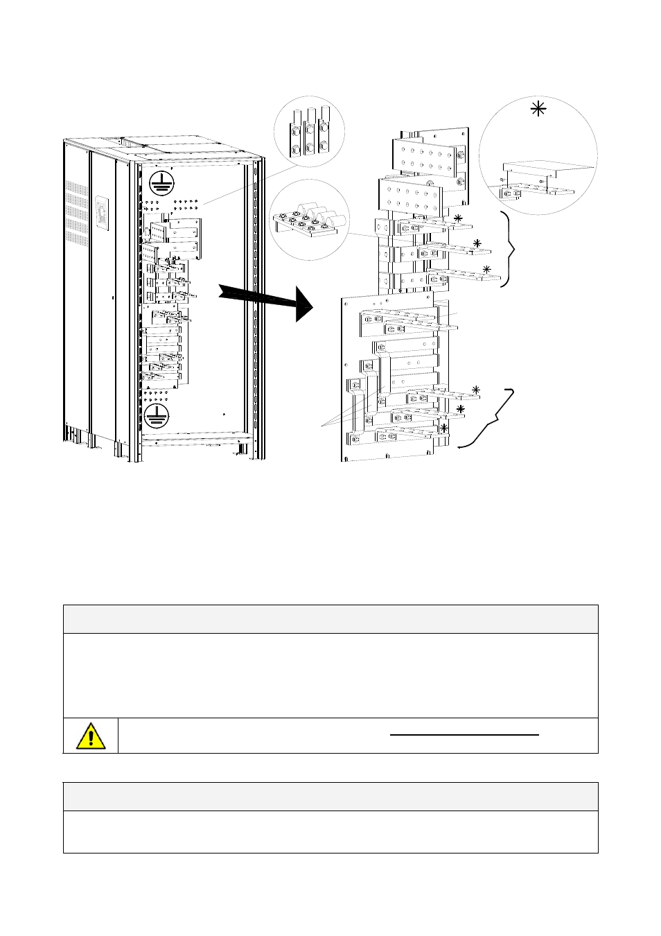
3.9.2 Power connection with common input utility
-
+
Neutral Load
Neutral Utility (Bypass)
SG
S_
75
0_U
P
S
connec
tio
n
common_G
E_01
_U
S
PE Input Utility
PE Load
Typical installation using
common NEMA two hole lugs
PE Load
PE Input Utility
LOAD
L3
1 - INPUT UTILITY
RECTIFIER & BYPASS
L1-1
L2-1
L3-1
Typical installation using
common NEMA two hole lugs
L2
L1
bus bars are done, the
PHASE BARRIER NOMEX SHEET
must be screwed onto the bus bars
After cable connections to the
wit 2 bolts M4x10
BR
1,
BR
2 a
nd
BR3
Fig. 3.9.2-1 SG Series 750 & SG Series 750 T12 power connections Common Input Utility
Use M12x35 bolts for the cable connections on INPUT / OUTPUT Power Wiring Bus Bars.
Cable terminations are to the Rectifier Input / Output Bus Bars as shown above.
Connect wire to the Bus Bars using appropriate tools and appropriate torque.
Torque specification for two hole lugs on Bus Bars: see Section 3.9.1.
Common Input Rectifier / Bypass
L1-1
Rectifier + Bypass Phase A
L2-1
Rectifier + Bypass Phase B
L3-1
Rectifier + Bypass Phase C
N
Utility Neutral (Bypass)
PE Input Utility
Ground
The interconnection bus bars BR1, BR2 and BR3 MUST REMAIN CONNECTED (see Fig.
3.9.3-3).
Output Load
L1
Load Phase A
L2
Load Phase B
L3
Load Phase C
N
Load Neutral
PE Load
Load Ground