3 programmable input free contacts, 4 gen set signaling (gen on), Programmable input free contacts – GE Industrial Solutions SG Series 750 T12 UL S2 Installation Guide User Manual
Page 47: Gen set signaling (gen on), Terminals xa
Modifications reserved
Page 47/49
OPM_SGS_ISG_M75_M75_2US_V010.doc
Installation Guide SG Series 750 UL S2 & SG Series 750 T12 UL S2
4.1.3 Programmable input free contacts
Some programmable UPS functions (indicated in Section 4.1), can be activated by closing an external
contact, if connected, on:
X1 / 10, 21
or
J2 / 10, 23
User Input 1 (default = Not used)
X1 / 11, 22
or
J2 / 11, 24
User Input 2 (default = Emergency GEN ON)
4.1.4 Gen Set Signaling (GEN ON)
If an emergency generator set supplies the UPS in case of Mains Failure and the generator is
considerably unstable in frequency, it should be suitable to install the signal “Generator ON” on X1 / 11,
22 or J2 / 11, 24). See Fig. 4.1-1 / X1 and J2.
Since the Parameter for of the reading of the Generator function is password protected, call the nearest
Service Center for it's activation.
When this contact closes, it changes certain (programmable) functions such as:
• Enabling or disabling of synchronization and consequently the Load transfer to generator.
• Reduction or elimination or delay of Battery recharging during the generator operation.
Additionally, when the “Generator ON” input contact is closed, the UPS will inhibit eBoost™ Operation
Mode and revert to double-conversion operation.
In a parallel system a separate NO (Normally Open) contact must be connected to
each individual unit.
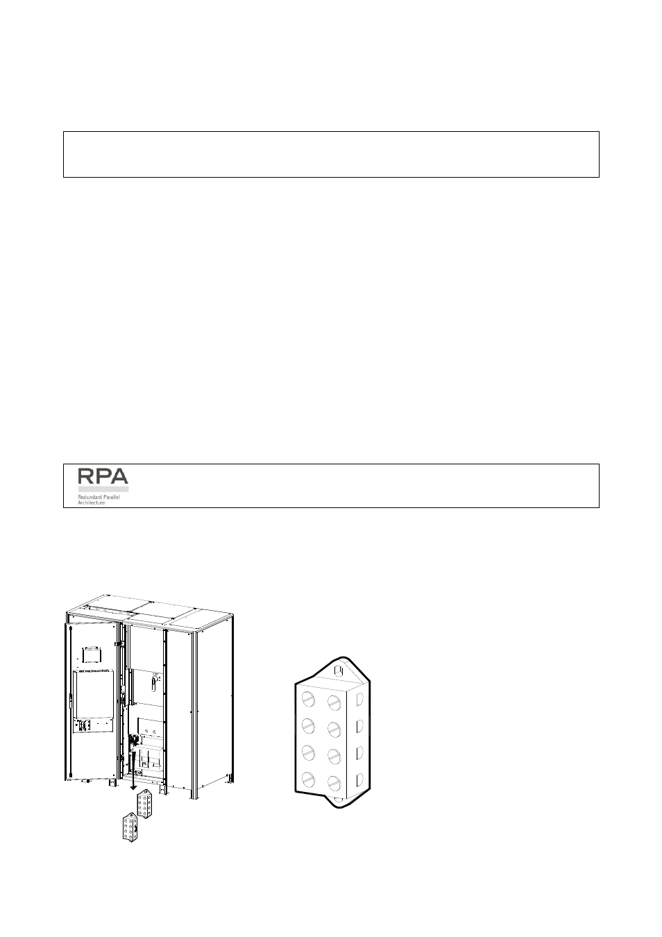
4.1.5 Auxiliary Power Supply (APS) 24Vdc and Battery Breaker Release
Terminals XA
SGS_750_S2_
UPS_XA-XB_01
Q1
XB
XA
1
2
3
4
4
3
2
1
2
3
1
4
2
3
1
4
2
14
15
34
16
17
56
19
20
89
18
7
22
11
1
21
10
12
12
13
S
G
S
_750_T
erm
in
als
X
B
_01
2
4
3
1
XA-1 24Vdc
XA-2 GND
XA-3 Positive
(+)
Battery Breaker Release
Voltage
XA-4 Negative
(-)
Battery Breaker Release
Voltage
Fig. 4.1.5-1 Terminals XA for connection 24Vdc and Battery Breaker Release