GE Industrial Solutions SG Series 750 T12 UL S2 Installation Guide User Manual
Page 30
Modifications reserved
Page 30/49
OPM_SGS_ISG_M75_M75_2US_V010.doc
Installation Guide SG Series 750 UL S2 & SG Series 750 T12 UL S2
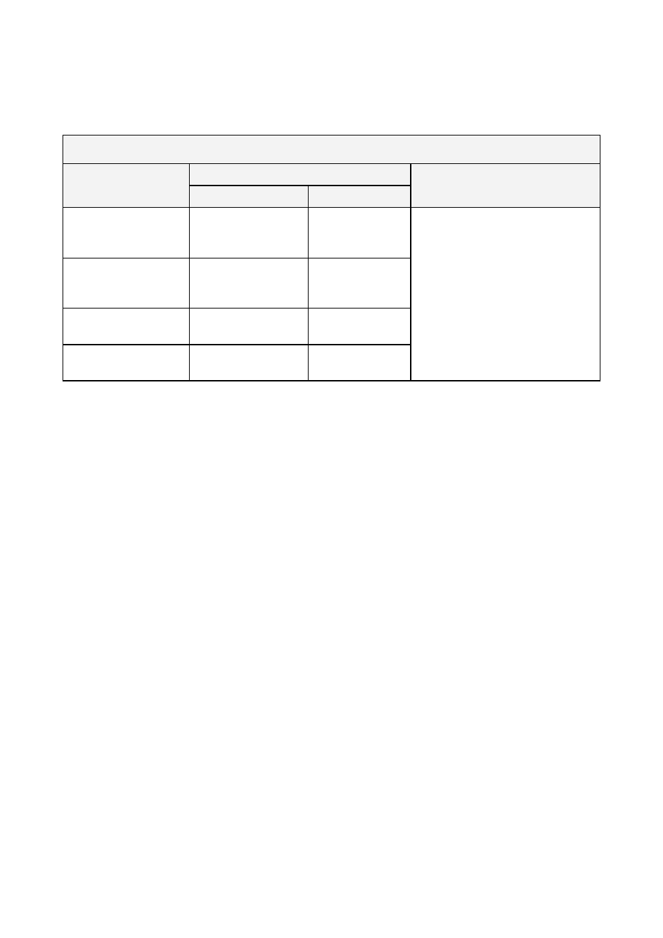
TERMINAL LUGS FOR FIELD WIRING CONNECTIONS
Provided for cable connections.
SG Series 750 & SG Series 750 T12
Rating
Connection type
Allowed cable sizes
Torque
Component
(A)
Rectifier Input
Neutral Bypass Input
5 x 500 MCM
428 LB-in
(B)
Bypass Input
Output
4 x 500 MCM
428 LB-in
(C)
DC + / DC -
6 x 600 MCM
428 LB-in
(D)
Grounding
4 x 500 MCM
428 LB-in
Use only UL LISTED components.
Use two holes lug component
(see Fig. 3.9.2-1 and Fig. 3.9.3-1).
Connection type A
20 Lugs are used in total for each unit:
15 are used for AC Rectifier input (3 lines).
5 are used for Neutral bypass input.
Terminal lugs are secured to metal plate or to bus bars by means of two bolts.
Connection type B
28 Lugs in total are used for each unit:
12 are used for AC Bypass input (3 Lines)
16 are used for AC Output (3 Lines and Neutral)
Terminal lugs are secured to metal plate or to bus bars by means of two bolts.
Connection type C
12 Lugs in total are used for each unit:
12 are used for DC input (positive and Negative input)
Terminal lugs are secured to metal plate or to bus bars by means of two bolts.
Connection type D
3 Lugs in total are used for each unit:
One is used for input Grounding.
One is used for output Grounding
One is used for battery cabinet grounding
Terminal Lugs are secured to chassis by means of two bolts.