1opening for top cable entry (*), 2opening for bottom cable entry (*), 3bus bars for utility input and load output – GE Industrial Solutions SG Series 750 T12 UL S2 Installation Guide User Manual
Page 10: 4bus bars for external battery connection, Cr1 connectivity rack with a customer interface, Ss service socket 120vac / 6a, Xb terminals for epo connection
Modifications reserved
Page 10/49
OPM_SGS_ISG_M75_M75_2US_V010.doc
Installation Guide SG Series 750 UL S2 & SG Series 750 T12 UL S2
2.3
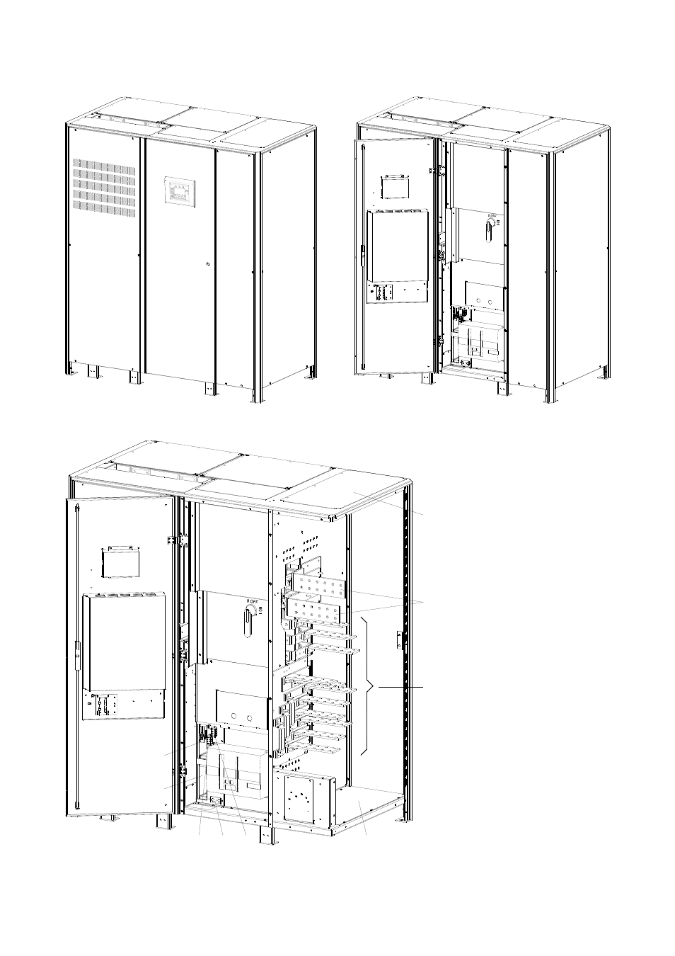
RECTIFIER CABINET LAYOUT SG Series 750 & SG Series 750 T12
SGS_750_UPS_
Rectifier cabinet_
GE_01
Fig. 2.3-1 Rectifier cabinet general view
SGS_750_S2_
UPS_Rectifier c
abinet_GE_02
Q1
2
14
15
34
16
17
56
19
20
89
18
7
22
11
1
21
10
12
12
13
4
1
3
2
4
1
3
2
Fig. 2.3-2 Rectifier cabinet general view with open doors
SGS_750_UPS
_Rectifier cabin
et_GE_03b
Q1
4
1
3
XB
XA
SS
CR1
CR2
2
14
15
34
16
17
56
19
20
89
18
7
22
11
1
21
10
12
12
13
3
4
2
1
2
3
1
4
2
Fig. 2.3-3 General rectifier cabinet view without protection panels
1
Opening for top cable
entry (*)
2
Opening for bottom
cable entry (*)
3
Bus bars for Utility
input and Load output
4
Bus bars for external
Battery connection
CR1 Connectivity Rack with
a Customer Interface
CR2 Connectivity Rack for
additional Customer
Interface
SS
Service socket 120Vac
/ 6A
XA Terminals for 24Vdc
Auxiliary Power Supply
connection and Battery
Breaker Release
XB Terminals for EPO
connection
*) Remove this panel or
provide means to capture
metal filings from cutting
conduit entry holes.