Rectifier cabinet, Front side – GE Industrial Solutions SG Series 750 T12 UL S2 Installation Guide User Manual
Page 16
Modifications reserved
Page 16/49
OPM_SGS_ISG_M75_M75_2US_V010.doc
Installation Guide SG Series 750 UL S2 & SG Series 750 T12 UL S2
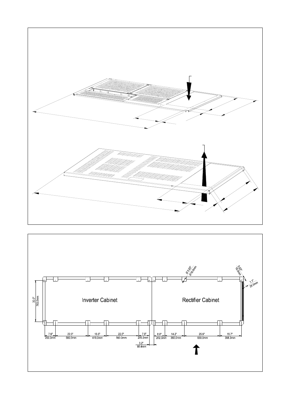
SG Series 750 & SG Series 750 T12 openings for input and output cable connections
SG Series 750 & SG Series 750 T12 openings are provided on the top and the bottom of the rectifier
cabinet for the connection of input and output cables.
Pay attention to the position of these openings, when choosing the placement of the UPS.
These openings are covered with a protective plate.
Utility input
Output Load
Battery
SGS_750_UPS v
iew top_01US
Rectifier cabinet
900
mm
35.
43"
145
mm
730
mm
28.
74"
2.09"
5.7
1"
349mm
13.74"
66.93"
1700mm
53mm
NOTE!
Remove this panel or provide
means to capture metal filings
from cutting conduit entry holes
Fig. 3.4.1-2 SG Series 750 & SG Series 750 T12 opening on top of the cabinet for input & output cables
Utility input
Output Load
Battery
SGS_750_UPS view
bottom_01US
28
.74
"
10
8m
m
4.2
5"
86
3m
m
33
.98
"
73
0m
m
1663mm
65.47"
349mm
13.74"
28mm
1.1"
Rectifier cabinet
NOTE!
Remove this panel or provide
means to capture metal filings
from cutting conduit entry holes
Fig. 3.4.1-3 SG Series 750 & SG Series 750 T12 opening on the bottom of the cabinet for input & output cables
SG Series 750 & SG Series 750 T12 fixing of the UPS cabinet on the floor
The UPS cabinet is free standing and normally does not require to be bolted to the floor.
The UPS cabinet can be fixed however to the floor by bolting it with the supporting blocks to the
floor. See Fig. 3.4.1-4.
Front side
SGS_750_UPS view bottom_02aUS
Fig. 3.4.1-4 SG Series 750 & SG Series 750 T12 fixing of the UPS cabinet on the floor