3 control bus cable location, Control bus cable location, Next parallel unit – GE Industrial Solutions SG Series 750 T12 UL S2 Installation Guide User Manual
Page 42: Ab ja ja2 jb2 jb1 ja1 jb
Modifications reserved
Page 42/49
OPM_SGS_ISG_M75_M75_2US_V010.doc
Installation Guide SG Series 750 UL S2 & SG Series 750 T12 UL S2
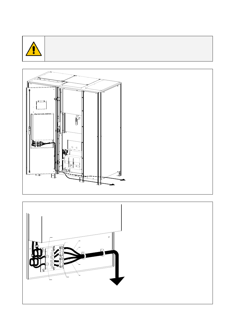
3.10.3 Control bus cable location
WARNING !
This operation must be performed by QUALIFIED SERVICE PERSONNEL ONLY before
the initial start-up.
ENSURE THAT THE UPS INSTALLATION IS COMPLETELY POWERED DOWN.
SGS_750_RPA
control bus cab
le_GE_01a_US
Q1
Next parallel unit
Rectifier cabinet
18
2
19
20
89
7
22
11
1
21
10
2
1
2
3
4
3
4
14
15
34
16
17
56
12
12
13
1
Fig. 3.10.3-1 View electronic module on intermediate unit
Access to the control bus
connection.
The control bus connection
between parallel units must be
made on the electronic module
“P34 – Bus Interface (IM0048)”
situated at the inside of the UPS
door.
S
G
S
_750_R
P
A
control bus cable_02U
S
Next parallel unit
A
B
JA
JA2
JB2
JB1
JA1
JB
Fig. 3.10.3-2 Front view electronic module on intermediate unit
Control bus cables connection.
• Plug the cables JA (1/2/3/4/5)
and JB (1/2/3/4/5) onto the RJ
connectors JA and JB located
on parallel bus PCB “P34 – Bus
Interface (IM0048)” (going to
“P13 – RPA Board” J52(A) and
J62(B)).
•
Fix both cables JA (1/2/3/4/5)
and JB (1/2/3/4/5) to parallel
bus socket connecting the
cable shield to ground by
means the cable clamps “A“.