Specifications, Installation category, Table 1 specifications – GE Industrial Solutions CPS3200U User Manual
Page 8
CPS3200U Upstream System – 23” Product Manual
CPS3200U
CC848779826 r09 December 2013
8
Specifications
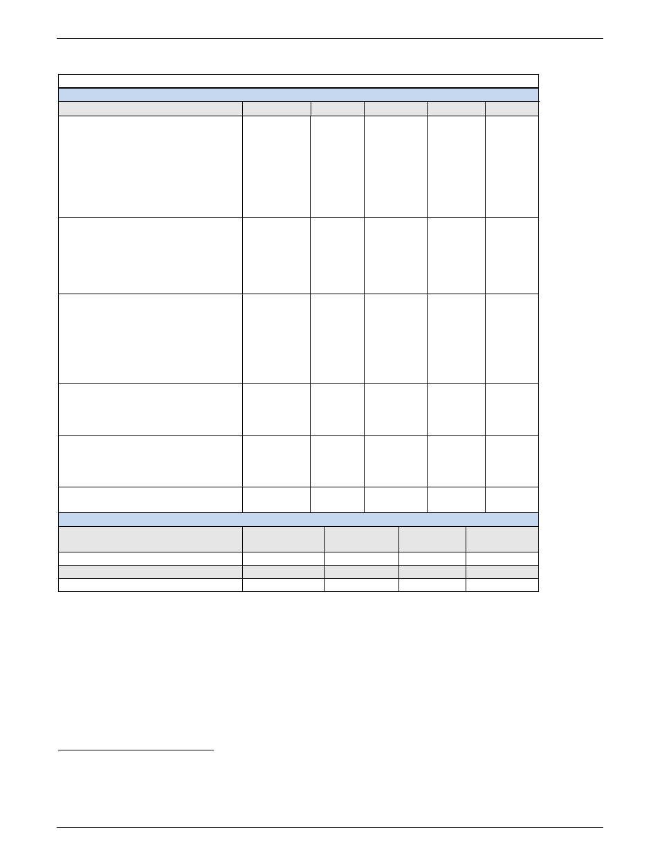
Table 1 Specifications
Electrical
Parameter
Symbol
Min
Typical
Max
Unit
Input Voltage
Operating Continuous
Non-operating, No Damage
V
I
-40
0
-52.8
-60
-40
Vdc
Transient (@ duration =)
5 Seconds
10 ms (
rise and fall rate of 10V/ms)
10 µs
1 µs
V
tr
V
tr
V
tr
V
tr
-65
-75
-100
-200
Vdc
Input Current - (per half shelf
at 97.7W on all circuits)
V
IN
= 54.4V
I
IN
34.7
Adc
V
IN
= 52.1V
I
IN
36.2
Adc
V
IN
= 42.6V
I
IN
44.3
Adc
V
IN
= 40.0V
I
IN
47.2
Adc
Temperature
Normal Operating Ambient
Temperature at 150 lfm airflow
T
A
-40
50
°C
Operating Ambient Temperature
at higher (TBD) airflow
T
A
-40
75
°C
Cold Start Temperature
T
A
-40
°C
Storage Temperature
T
stg
-55
85
°C
Power – per C/L Card
Input Power at -42.6 Vdc input
Pin
240
W
Power Dissipation
Pdiss
21
40*
W
Output Power
Pout
200
W
Output
Voltage – line to line
V
O
378
380
382
Vdc
Power – per C/L circuit
P
O
95.0
97.7
100
W
Current – per C/L circuit
I
OUT
251
257
262
mA
Isolation
Input to Output Voltage
1500
Vdc
Physical
Height
in (mm)
Width
in (mm)
Depth
in (mm)
Weight
lb (kg)
23-Inch Shelf
3.5 (88.9)
21.4 (543.6)
12 (304)
30 (13.6)
Fan Shelf
3.5 (88.9)
21.4 (543.6)
12 (304)
20 (9.0)
1U Baffle
1.75 (44.4)
21.4 (543.6)
12 (304)
4 (1.8)
Installation Category
CPS3200U output circuits are suitable for connection to telephone lines that are equipped with primary lightning
protectors consistent with UL 497. The user must provide protection on each copper pair to a level corresponding to a
CommScope 3C*EW Gas tube primary protector or equivalent gas tube protector [For example: 3C3EW provides the
part in a red color]. This protector has a voltage breakdown range of 265-465 Volts and an impulse spark over range of
<265-700 Volts. The 5-Pin protector must be marked as a “special circuit” consistent with the marking protocol in the
users network. Protectors are provided by the telco customer.
Network equipment and components along the powering circuit shall have suitable insulation resistance at 200 Vdc
from each conductor to ground and a total insulation resistance suitable for 400 Vdc from line to line.
2
Max = Absolute Maximum Rating
3
These are maximum situations with each circuit loaded to 100W. No actual or engineered application would load
every circuit to this level. In the absence of detailed information about the network we would recommend using the
typical dissipation value of 21 Watts for most applications with 30W per card for highly loaded networks.