Ground the shelf, Attach the load wiring, Figure 7 grounding converter shelf – GE Industrial Solutions CPS3200U User Manual
Page 18
CPS3200U Upstream System – 23” Product Manual
CPS3200U
CC848779826 r09 December 2013
18
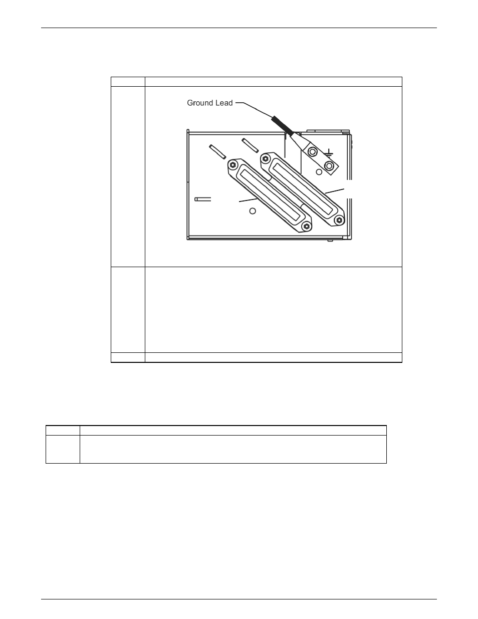
Ground the Shelf
The next step is to ground the shelf to earth ground. This is an important safety step since each converter relies on this
connection for proper ground fault detection.
Step
Action
1.
Run and connect the framework ground lead as shown.
Figure 7 Grounding Converter Shelf
2.
Use 6GA conductor minimum and connect to the safety grounding point
(frame ground, or main ground bar) per local practice. Additionally apply
NO-OX ID to all bare metal connections if required by local practice. Lugs
are ¼ inch studs on 5/8 inch centers.
Lugs for 6AWG conductor are as follows or available equivalent:
T&B 6STR30W
Burndy YAV6C-L2TC14-FX
3.
Torque connections to 4 Nm or 35 in-lbs.
Attach the Load Wiring
Provide a circuit from each converter into the designated network telephone pairs. Follow the steps in the table below
to attach load wiring to the CPS3200U shelf.
Step
Action
1.
The wiring assignment information in the following table provides the appropriate
connections for each circuit. A cable should be provided with this pinout configuration to
terminate the J1 and J2 output connectors on the CPS3200U Shelf.
• Wireset Connector: RJ-21 type 50 pin plug:
• 22 AWG solid or stranded AMP 552173-1 or equivalent.
• 24 AWG solid or stranded or 26 AWG solid AMP 229974-1 or equivalent.
• The connector shall be arranged with a right angle housing such that the cable exits to the pin 1 side.
J2, 9-16
J1, 1-8