Apply dc power, Recognizing normal states, Figure 27 qs982a faceplate and leds – GE Industrial Solutions CPS3200U User Manual
Page 30
CPS3200U Upstream System – 23” Product Manual
CPS3200U
CC848779826 r09 December 2013
30
Apply DC Power
Apply DC power by turning on input fuses or circuit breakers. Power the fan shelf and the converter shelf
simultaneously. The system will operate from voltages between -40 and -60 volts with normal status at feed voltages
between -52 Volts and -54.5 Volts.
Fault LEDs will flash red until communications is established between the alarm card and each converter. The alarm
card will flash its fault LED until connection is confirmed to the QS941, if present. If no QS941 is present the alarm cards
will flash their red LED until they are set to address 0, 0 as described in the Set Shelf ID and Attach Alarm Wiring
section.
Complete UL 60950-21 step 7 under Inspect the Network to test each circuit after DC power is applied.
Recognizing Normal States
Once power is provided to the CPS3200U system the LEDs on the converters will illuminate. Understanding what the
LEDs mean allows one to recognize normal states and diagnose abnormal states.
Step
Action
1.
Observe the LEDs.
2.
Use the state table below to determine the state of the system and required corrective actions
if needed.
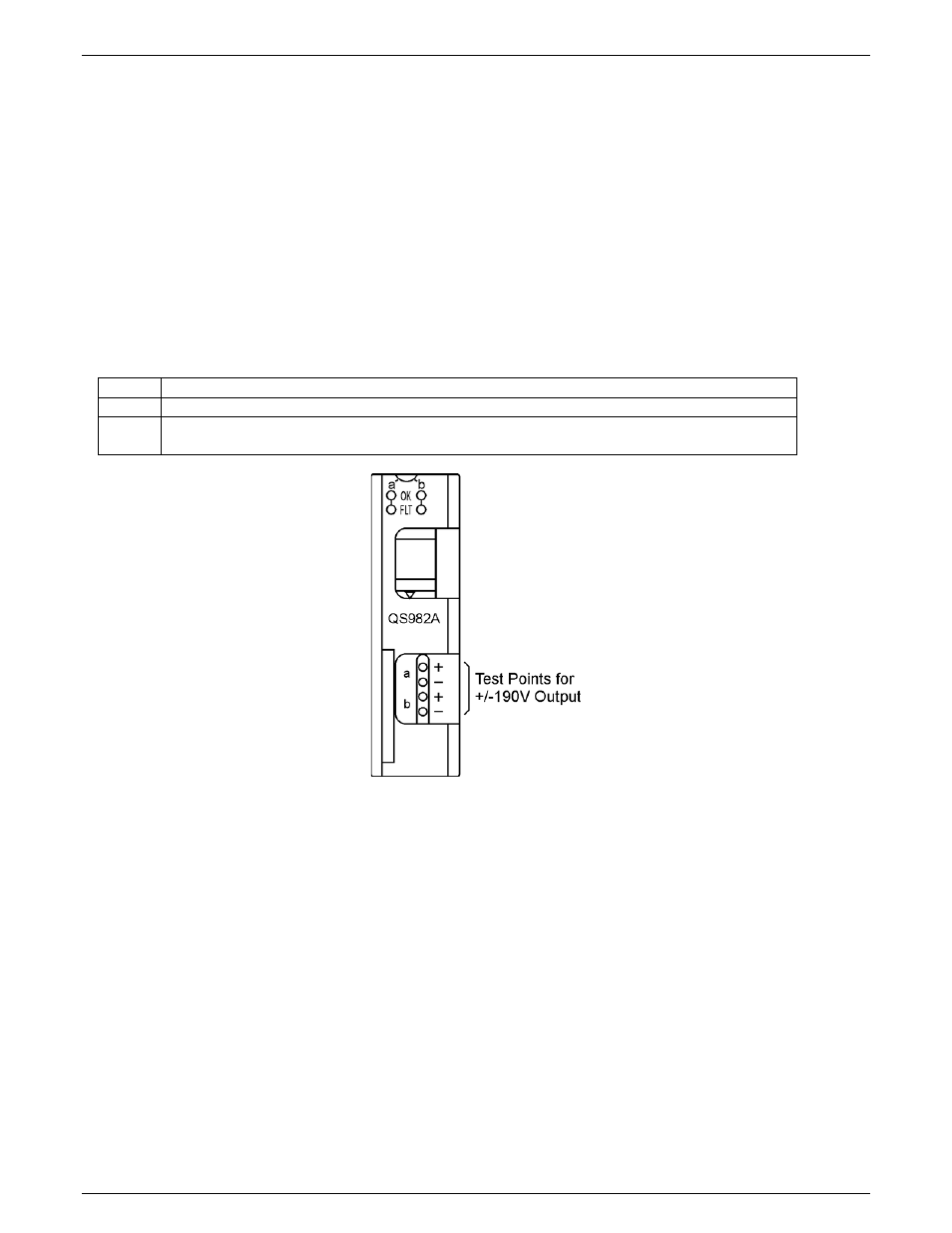
Figure 27 QS982A Faceplate and LEDs
(Note: Test points work best if each voltage is measured with respect to ground)