Feature specifications – GE Industrial Solutions EQW010-040 Series (Eighth-Brick) User Manual
Page 5
Data Sheet
October 5, 2013
EQW010-040 Series Power Modules
36 – 75Vdc Input; 1.0 to 12.0Vdc Output; 10 to 40A Output Current
LINEAGE
POWER
5
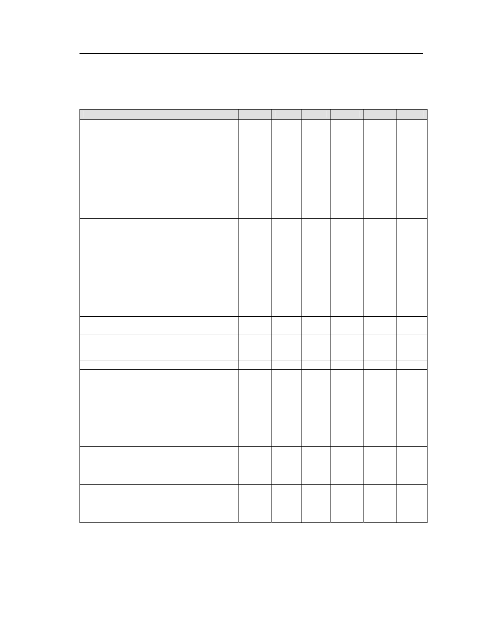
Feature Specifications
Unless otherwise indicated, specifications apply over all operating input voltage, resistive load, and temperature
conditions. See Feature Descriptions for additional information.
Parameter
Device
Symbol
Min
Typ
Max
Unit
Remote On/Off Signal Interface
(V
IN
=V
IN, min
to V
IN, max
; open collector or equivalent,
Signal referenced to V
IN-
terminal)
Negative Logic: device code suffix “1”
Logic Low = module On, Logic High = module Off
Positive Logic: No device code suffix required
Logic Low = module Off, Logic High = module On
Logic Low - Remote On/Off Current
All
I
on/off
1.0 mA
Logic Low - On/Off Voltage
All
V
on/off
-0.7
1.2 V
dc
Logic High Voltage – (Typ = Open Collector)
All
V
on/off
5
V
dc
Logic High maximum allowable leakage current
All
I
on/off
10
μA
Turn-On Delay and Rise Times
(I
O
=I
O, max ,
V
IN
=V
IN, nom,
T
A
= 25
o
C)
Case 1: On/Off input is set to Logic Low (Module
ON) and then input power is applied (T
delay
from
instant at which V
IN
= V
IN, min
until Vo=10% of V
O,set
)
All
B*
T
delay
T
delay
―
―
20
25
25
30
msec
msec
Case 2: Input power is applied for at least 1 second
and then the On/Off input is set from OFF to ON (T
delay
=
from instant at which V
IN
=V
IN, min
until V
O
= 10% of V
O, set
).
All
B*
T
delay
T
delay
―
―
5
25
10
30
msec
msec
Output voltage Rise time (time for Vo to rise from 10%
of V
o,set
to 90% of V
o, set
)
All T
rise
― 8 12
msec
Output voltage Rise time (time for Vo to rise from 10%
of V
o,set
to 90% of V
o, set
with max ext capacitance)
All T
rise
― 8 12
msec
Output voltage overshoot – Startup
All
― 3
%
V
O, set
I
O
= I
O, max
; V
IN
=V
IN, min
to V
IN, max
, T
A
= 25
o
C
Remote Sense Range
G, Y, M,
P, S1R0
V
SENSE
0.25 Vdc
(Max voltage drop is 0.5V)
B*, A, F
V
SENSE
10 %
V
O, set
Output Voltage Adjustment Range
All*
80
110
% V
O, set
Output Overvoltage Protection
B V
O, limit
14
16 V
dc
A
V
O, limit
5.7
6.5 V
dc
F
V
O, limit
3.8
4.6 V
dc
G
V
O, limit
2.9
3.4 V
dc
Y
V
O, limit
2.3
2.6 V
dc
M
V
O, limit
1.8
2.2 V
dc
P
V
O, limit
1.4
1.6 V
dc
S1R0
V
O, limit
1.2
1.4 V
dc
Input Undervoltage Lockout
All
V
UVLO
Turn-on Threshold
30 34.5 36 V
dc
Turn-off Threshold
30 32
V
dc
Hysterisis
1.5
2
V
dc
Input Overvoltage Lockout
All
V
OVLO
Turn-on Threshold
80
V
dc
Turn-off Threshold
75 79 83 V
dc
Hysterisis
2
3.5
V
dc
* Note: 12.0V
O
(B) device codes have an adaptable extended Turn-On Delay interval, T
delay
, as specified for B* devices. The extended T
delay
will occur
when a 12V
O
module restarts following either 1) the rapid cycling of Vin from normal levels to less than the Input Undervoltage Lockout and then back
to normal; or 2) toggling the on/off signal from on to off and back to on without removing the input voltage. The normal Turn-On Delay interval, T
delay
,
as specified for All Devices, will occur whenever a 12V
O
module restarts with input voltage removed from the module for the preceding 1 second.
12.0V
O
(B) also achieves +10% V
O, set
Remote Sense drop or trim up to 110% V
O, set
only above Vin = 40V
dc
.