Surface mount information – GE Industrial Solutions EQW010-040 Series (Eighth-Brick) User Manual
Page 19
Data Sheet
October 5, 2013
EQW010-040 Series Power Modules
36 – 75Vdc Input; 1.0 to 12.0Vdc Output; 10 to 40A Output Current
LINEAGE
POWER
19
Surface Mount Information
(continued)
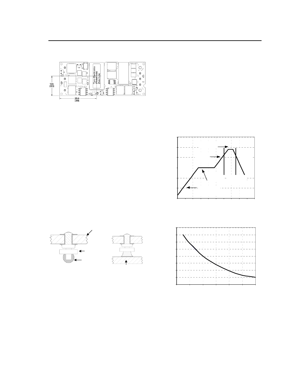
Figure 65. Pick and Place Location.
Nozzle Recommendations
The module weight has been kept to a minimum by
using open frame construction. Even so, these
modules have a relatively large mass when compared
to conventional SMT components. Variables such as
nozzle size, tip style, vacuum pressure and placement
speed should be considered to optimize this process.
The minimum recommended nozzle diameter for
reliable operation is 6mm. The maximum nozzle outer
diameter, which will safely fit within the allowable
component spacing, is 9 mm.
Oblong or oval nozzles up to 11 x 9 mm may also be
used within the space available.
Reflow Soldering Information
The surface mountable modules in the EQW family
use our newest SMT technology called “Column Pin”
(CP) connectors. Figure 66 shows the new CP
connector before and after reflow soldering onto the
end-board assembly.
EQW Board
Insulator
Solder Ball
End assembly PCB
Figure 66. Column Pin Connector Before and After
Reflow Soldering.
The CP is constructed from a solid copper pin with an
integral solder ball attached, which is composed of
tin/lead (Sn
63
/Pb
37
) solder for non-Z codes, or
Sn/Ag
3.8
/Cu
0.7
(SAC) solder for –Z codes. The CP
connector design is able to compensate for large
amounts of co-planarity and still ensure a reliable
SMT solder joint. Typically, the eutectic solder melts
at 183
o
C (Sn/Pb solder) or 217-218
o
C (SAC solder),
wets the land, and subsequently wicks the device
connection. Sufficient time must be allowed to fuse
the plating on the connection to ensure a reliable
solder joint. There are several types of SMT reflow
technologies currently used in the industry. These
surface mount power modules can be reliably
soldered using natural forced convection, IR (radiant
infrared), or a combination of convection/IR.
The following instructions must be observed when
SMT soldering these units. Failure to observe these
instructions may result in the failure of or cause
damage to the modules, and can adversely affect
long-term reliability.
Tin Lead Soldering
The recommended linear reflow profile using Sn/Pb
solder is shown in Figure 67 and 68. For reliable
soldering the solder reflow profile should be
established by accurately measuring the modules CP
connector temperatures.
RE
F
LO
W
T
E
MP
(
C)
0
50
100
150
200
250
300
Preheat zo ne
max 4
o
Cs
-1
So ak zo ne
30-240s
Heat zo ne
max 4
o
Cs
-1
Peak Temp 235
o
C
Coo ling
zone
1-4
o
Cs
-1
T
lim
above
205
o
C
REFLOW TIME (S)
Figure 67. Recommended Reflow Profile for
Tin/Lead (Sn/Pb) process.
M
A
X T
E
M
P
SO
LD
E
R
(
C)
200
205
210
215
220
225
230
235
240
0
10
20
30
40
50
60
Figure 68. Time Limit, T
lim
, Curve Above 205
o
C for
Tin/Lead (Sn/Pb) process.