Feature descriptions – GE Industrial Solutions EQW010-040 Series (Eighth-Brick) User Manual
Page 17
Data Sheet
October 5, 2013
EQW010-040 Series Power Modules
36 – 75Vdc Input; 1.0 to 12.0Vdc Output; 10 to 40A Output Current
LINEAGE
POWER
17
Feature Descriptions
(continued)
following the over current condition. The module can
be restarted by cycling the dc input power for at least
one second or by toggling the remote on/off signal for
at least one second. If the unit is configured with the
auto-restart option (4), it will remain in the hiccup
mode as long as the overcurrent condition exists; it
operates normally, once the output current is brought
back into its specified range. The average output
current during hiccup is 10% I
O, max
.
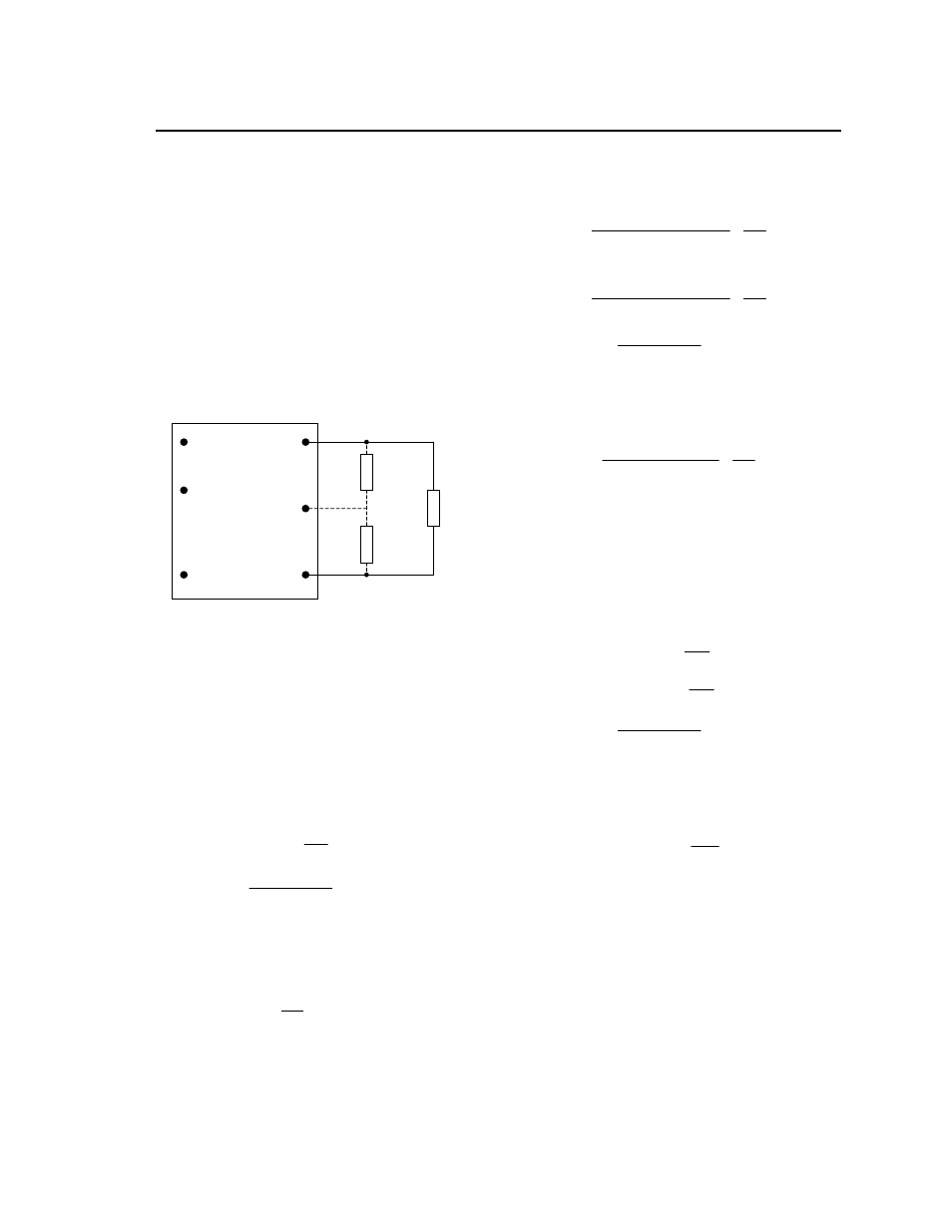
Output Voltage Programming
Trimming allows the output voltage set point to be
increased or decreased, this is accomplished by
connecting an external resistor between the TRIM pin
and either the V
O
(+) pin or the V
O
(-) pin.
V
O
(+)
V
O
TRIM
V
O
(-)
R
trim-down
LOAD
V
IN
(+)
ON/OFF
V
IN
(-)
R
trim-up
Figure 62. Circuit Configuration to Trim Output
Voltage.
Connecting an external resistor (R
trim-down
) between
the TRIM pin and the Vo(-) (or Sense(-)) pin
decreases the output voltage set point. To maintain
set point accuracy, the trim resistor tolerance should
be ±1.0%.
The following equation determines the required
external resistor value to obtain a percentage output
voltage change of ∆%
For output voltage: 1.0V to 12V
22
.
10
%
511
down
trim
R
Where
100
%
,
,
set
o
desired
set
o
V
V
V
For example, to trim-down the output voltage of 2.5V
module (EQW035A0G/G1) by 8% to 2.3V, Rtrim-
down is calculated as follows:
8
%
22
.
10
8
511
down
trim
R
655
.
53
down
trim
R
Connecting an external resistor (R
trim-up
) between the
TRIM pin and the V
O
(+) (or Sense (+)) pin increases
the output voltage set point. The following equations
determine the required external resistor value to
obtain a percentage output voltage change of ∆%:
For output voltage: 1.5V to 12V
22
.
10
%
511
%
225
.
1
%)
100
(
11
.
5
, set
o
up
trim
V
R
For output voltage: 1.0V to 1.2V
22
.
10
%
511
%
6
.
0
%)
100
(
11
.
5
, set
o
up
trim
V
R
Where
100
%
,
,
set
o
set
o
desired
V
V
V
For example, to trim-up the output voltage of 1.2V
module (EQW040A0P/P1) by 5% to 1.26V, R
trim-up
is
calculated is as follows:
5
%
22
.
10
5
511
5
6
.
0
)
5
100
(
2
.
1
11
.
5
up
trim
R
2
.
102
up
trim
R
Alternative voltage programming for output
voltage: 1.0V to 1.2V (-V Option)
An alternative set of trimming equations is available
as an option for 1.0V and 1.2V output modules, by
ordering the –V option. These equations will reduce
the resistance of the external programming resistor,
making the impedance into the module trim pin lower
for applications in high electrical noise applications.
2
%
100
down
trim
R
%
100
up
trim
R
Where
100
%
,
,
set
o
set
o
desired
V
V
V
For example, to trim-up the output voltage of 1.2V
module (EQW040A0P/P1-V) by 5% to 1.26V, R
trim-up
is calculated is as follows:
5
%
5
100
up
trim
R
0
.
20
up
trim
R
The value of the external trim resistor for the optional
–V 1.2V module is only 20% of the value required with
the standard trim equations.