Appendix, 1. application diagrams, Basic diagram with linear ramp – GE Industrial Solutions ASTAT-CD Plus User Manual
Page 31
M
3 ~
L1
L2
L3
1 L1 3 L2 5 L3
A1 A2
B1 B2
A1 A2
B1 B2
57
57
57
6
8
12 11 14
23 24
33 34
1
2
Start
3
4
5
7
2 T1 4 T2 6 T3
9
Motor Thermistor
I3
I4
1r
2r
3r
Programmable Inputs
Programmable relay Outputs
TD RD SG
Control Voltage
110 / 120V AC
Control Voltage
220 / 240V AC
FLT (4)
DC1
DC1 (1)
Stop
Push-Button command (2)
6. Appendix
6-3
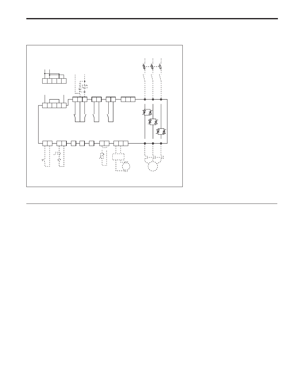
6-1. Application diagrams
Basic diagram with linear ramp
REMARKS:
(1) The isolation contactor DC1, is not required to perform
operation to the motor.
Be aware however that DC1 provides galvanic isolation
from the incoming line increasing the safety.
(2) In this example, Start and Stop command is provided by
push-buttons. Permanent command is allowed as well,
wiring 1, 2 and 57 terminals as shown on page 3-3.
(3) The output relays allow for direct action on contactors
according to ratings specified in page 3-2 of this manual.
(4)
The ASTAT-CD Plus is provided with an electronic motor
overload protection, which should be adequate protec-
tion for most of the applications.
An external overload relay should be used if required
by local codes or to protect the motor against current
unbalance.
(5) Linear ramp provided by "Dxxx" function. A tacho
generator must be used as feedback. Details given
bellow.
Linear ramp function. Programming steps
1. The linear ramp function may be enabled by setting
"Dxxx" to ON. In this case, linear ramp is independent of
the load.
This function needs the speed feedback provided by an
external tacho generator. Check section 4-6-2 for more
details.