Appendix, 1. application diagrams, Basic diagram – GE Industrial Solutions ASTAT-CD Plus User Manual
Page 29: Basic diagram with by-pass control
A1 A2
B1 B2
57
57
57
6
8
12 11 14
23 24
33 34
1
2
Start /Stop
(Permanent Command)
3
4
5
7
9
57
57
1
2
Start Stop
(Command by push-buttons)
Prog
ra
mmab
le
Inputs
Motor Ther
mistor
Input
T
acho f
eedbac
k
Analog Input
0-10V
Analog Output
V
+
-
-
+
I3
I4
1r
2r
3r
Programmable Inputs
Programmable Relay Outputs
TD RD SG
Tx
M2
Bypass
Rx Gr
Serial Comm.
RS232C
A1 A2
B1 B2
Control Voltage
110 / 120V AC
Control Voltage
Control Voltage
220 / 240V AC
DC2
DC1
M
3 ~
L1
L2
L3
1 L1 3 L2 5 L3
2 T1 4 T2 6 T3
M
3 ~
L1
L2
L3
1 L1 3 L2 5 L3
A1 A2
B1 B2
A1 A2
B1 B2
57
57
57
6
8
12 11 14
23 24
33 34
1
2
Start
3
4
5
7
2 T1 4 T2 6 T3
9
Motor Thermistor
I3
I4
1r
2r
3r
Programmable Inputs
Programmable relay Outputs
TD RD SG
Control Voltage
110 / 120V AC
Control Voltage
220 / 240V AC
FLT (4)
DC1
DC1 (1)
Stop
Push-Button command (2)
6. Appendix
6-1
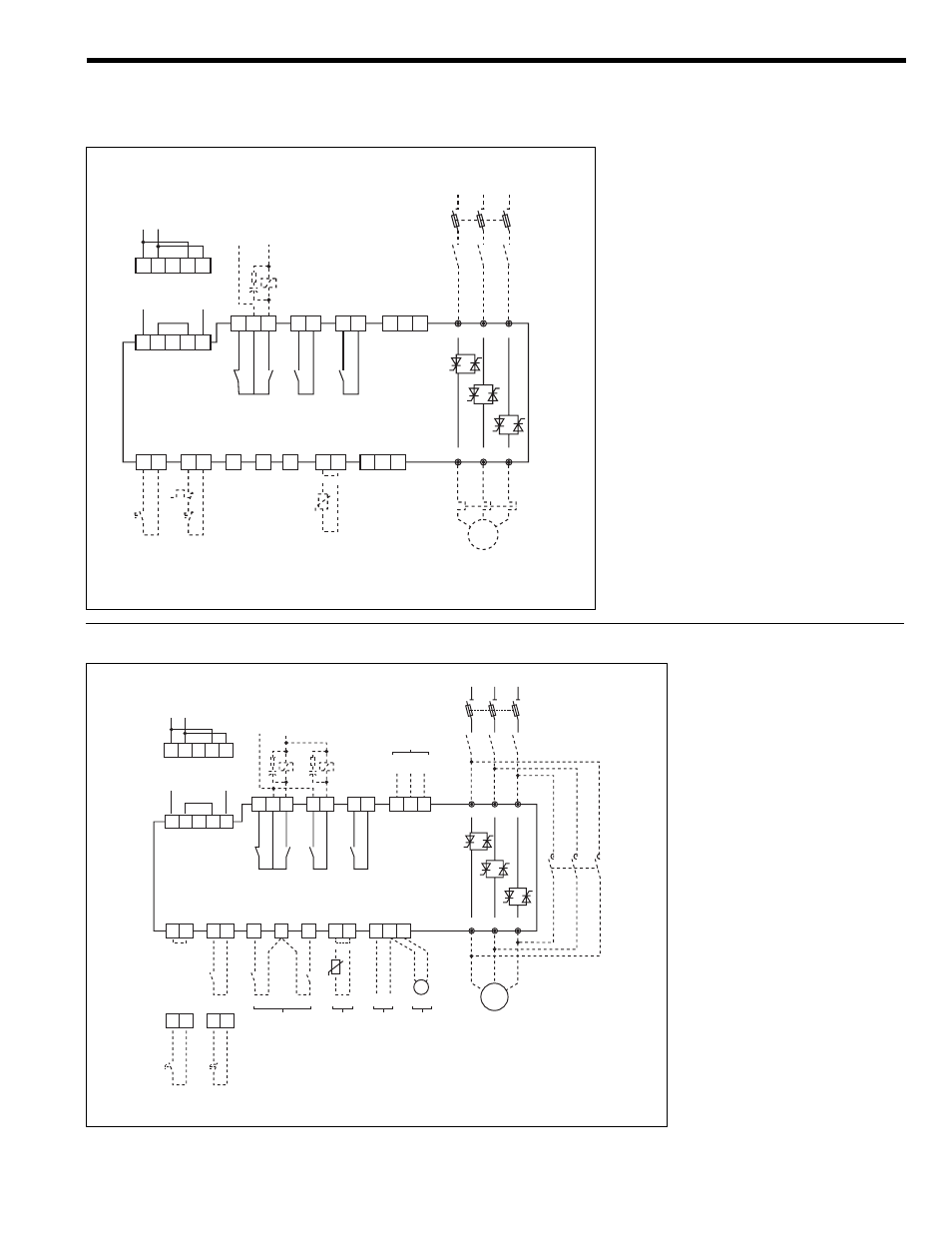
6-1. Application diagrams
Basic diagram
REMARKS:
(
1) The isolation contactor DC1, is not required to perform
operation to the motor.
Be aware however that DC1 provides galvanic
isolation from the incoming line increasing the safety.
(2) In this example, Start and Stop command is enabled
by push-buttons. Permanent command is allowed as
well, wiring 1, 2 and 57 terminals as shown on
page 3-3.
(3) The output relays allow for direct action on contactors
according to ratings specified on page 3-2 of this
manual.
(4) The ASTAT-CD Plus is provided with an electronic
motor overload protection, which should be adequate
protection for most of the applications.
An external overload should be used if required by
local codes or to protect the motor against current
unbalance.
Basic diagram with by-pass control
REMARKS:
(1) The isolation contactor DC1, is not re-
quired to perform operation to the motor.
Be aware however that DC1 provides gal-
vanic isolation from the incoming line in-
creasing the safety.
(2) In this example, Start and Stop command
is enabled by permanent command. Push-
button control is allowed as well, wiring 1,
2 and 57 terminals as shown on page 3-3.
(3) The output relays allow for direct action on
contactors according to ratings specified
in page 3-2 of this manual.
(4) CAUTION:
In by-pass mode an external overload
relay must be used.
(5) By-pass control using function "zxxx" and
external contactor DC2. Details given bel-
low.
By-pass control. Programming steps
1. The by-pass function may be enabled by
setting "zxxx" to ON. In this case the by-
pass is automatically done after starting.
An alternative, if "zxxx" is set to one of the
programmable inputs "I3" or "I4", the by-
pass may be controlled by one remote
signal (5). Check section 4-5-2 for more
details.
2. Once this function is enabled, the relay 2r
is automatically assigned to this function
(check section 4-6-3). This relay must be
used to control the by-pass contactor.