Installation, 6. thyristor check – GE Industrial Solutions ASTAT-CD Plus User Manual
Page 28
Symptom or Error & (Error Code)
Possible Cause
Measures to be taken
Synchronism loss
(Ex13)
Phase A, B, C thyristor
(Ex14)
(Ex15)
(Ex16)
Heatsink thermostat
(Ex17)
Motor thermistor
(Ex18)
Phase A, B, C loss
(Ex19)
(Ex20)
(Ex21)
Stalled rotor
(Ex22)
Check 1L1 phase
Check thyristor module
Check ground connections and voltage to ground
Poor ribbon cable connection
Check 2T1, 4T2 and 6T3 phases
No output phases
Short circuited thyristor
Phase 1L1 lost
Check for adequate ventilation
Check thermostat and wiring
Heatsink thermostat tripped by overheating or
defective
Check thermistor and wiring, if no thermistor
terminal 5 and 6 must be jumpered
Motor thermistor tripped by overheating or defective
Check power wire harness for 1L1, 3L2, 5L3,
2T1, 4T2 and 6T3
No input / output phases
Verify gate and cathode wire
harness. Verify thyristors
Defective thyristor or ribbon wire harness
loose or defective
Restart equipment and check for an appreciable loss in
motor speed at any time
Equipment detected stalled motor rotor
Internal error
(Ex23)
Long start time
(Ex25)
Long slow speed time
(Ex26)
Reduce time slow speed is engaged
Equipment has been in slow speed mode more
than 120 sec.
Check IC1 and IC8 are correctly inserted in their sockets.
Check for noise on control voltage power or line
Micro-controller malfunction
Increase current limit and / or acceleration
ramp time
Current limit condition present more than
2 x ta sec. or 240 sec.
(ta = acceleration ramp time)
5. Installation
L
S
10 ohms
3 to 6V
3 to 6V
Testing
lamp
1L1 (3L2 or 5L3)
2T1 (4T2 or 6T3)
5-4
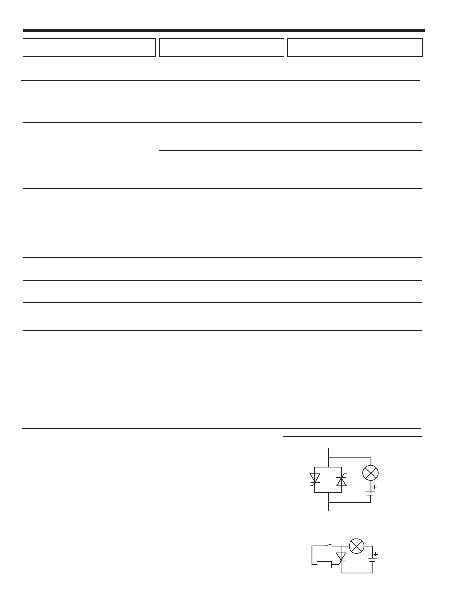
5-6. Thyristor check
S
hortcircuit
Use a testing lamp to check the defective power module between input and output phases.
If the lamp goes on, at least one of the thyristors has a short circuit.
With a tester, check the value or the R resistance between input and output of the same phase
(connector B on main PCB must be previously removed).
If R < 50K
Ω
, at least one of the thyristors is defective.
Open thyristor
With the simple assembly shown, the lamp should light when the S switch is closed and remain lit when open.
If not, the thyristor is defective.
Lock-out
(Ex27)
Check if settings are correct
This protection may be disabled
The time between startings is less that the
adjusted in parameter "LKxx"
Undervoltage
(Ex28)
Overvoltage
(Ex29)
Check if settings are correct.
This protection may be disabled
The line voltage exceeds of limit set in
parameters "UVxx" or "OVxx"
Undercurrent
(Ex30)
Overcurrent
(Ex31)
Check if settings are correct.
This protection may be disabled
The motor current exceeds of limit set in
parameters "UCxx" or "OCxx"
Retry
(Ex32)
Check last message "e1xx" and correct.
Be sure that retry settings are correct as well.
The retry feature could not re-start the motor
after a fault
Excessive load or excessive current during
starting
Verify overload conditions during starting time and
steady state.
Check settings in parameters "Nxxx", "Lxxx", and "oxxx"
Overload trip
(Ex11)
Check 1L1 phase and/or mains frequence
No 1L1 phase or frequence is out of range
Frequency error
(Ex10)
(admits 45Hz
≤
f main
≤
65Hz)