Data sheet, Manufacturer-specific pmbus, Commands – GE Industrial Solutions CP2000DC54-PE User Manual
Page 9
GE
Data Sheet
CP2000DC54-PE series dc-dc converter
Input: -40Vdc to -72Vdc; Outputs: ±54Vdc @ 2000W; 5Vdc @ 4W
August 20, 2013
©2013 General Electric Company. All rights reserved.
Page 9
Software programming of output voltage overrides the set
point voltage configured during power_up. The program no
longer looks at the ‘margin pin’ and will not respond to any
hardware voltage setting. The default state cannot be
accessed any longer unless power is removed from the DSP.
To properly hot-plug a power supply into a live backplane,
the system generated voltage should get re-configured into
either the factory adjusted firmware level or the voltage
level reconfigured by the margin pin. Otherwise, the voltage
state of the plugged in power supply could be significantly
different than the powered system.
Voltage margin range: 42V
DC
– 58 V
DC
.
A voltage programming example: The task: set the output
voltage to 50.45V
DC
The constants for voltage programming are: m = 400, b and
R = 0. Multiply the desired set point by the m constant,
50.45 x 400 = 20,180. Convert this binary number to its hex
equivalent: 20,180b = 4ED4h. Transmit the data LSB first,
followed by MSB,
0 x D44Eh.
Vout_OV_fault_limit (40h) :
This command sets the Output
Overvoltage Shutdown level.
Manufacturer-Specific PMBus
TM
Commands
Many of the manufacturer-specific commands read back
more than two bytes
.
If more than two bytes of data are
returned, the standard SMBus
TM
Block read is utilized. In this
process, the Master issues a Write command followed by
the data transfer from the power supply. The first byte of the
Block Read data field sends back in hex format the number
of data bytes, exclusive of the PEC number, that follows.
Analog data is always transmitted LSB followed by MSB. A
No-ack following the PEC byte signifies that the transmission
is complete and is being terminated by the ‘host’.
Read_status (D0h) :
This ‘manufacturer specific’ command
is the basic read back returning STATUS and ALARM register
data, output voltage, output current, and internal
temperature data in a single read.
1 8 1
8
1
S Slave
address Wr A Command
Code A
1
8
1 8 1
Sr Slave
address Rd A
Byte count = 9
A
8 1 8 1 8 1
Status-2 A Status-1 A Alarm-2 A
8
1 8 1 8 1
Alarm-1 A Voltage LSB
A
Voltage MSB
A
8 1 8
1 8 1
1
Current A Temperature A PEC NA P
Status and alarm registers
The content and partitioning of these registers is
significantly different than the standard register set in the
PMBus™ specification. More information is provided by
these registers and they are accessed rapidly, at once, using
the ‘multi parameter’ read back scheme of this document.
There are a total of four registers. All errors, 0 – normal, 1 –
alarm.
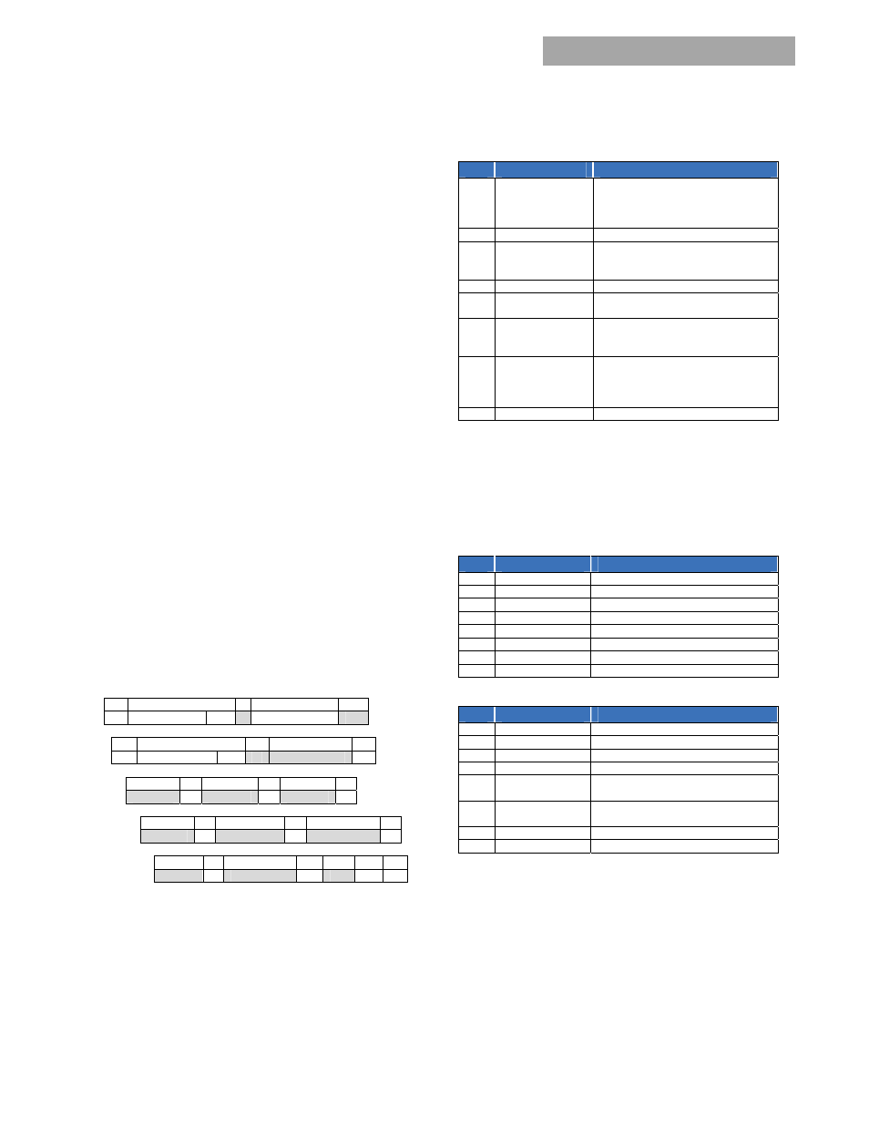
Status-2
Bit
Title
Description
7
PEC Error
Mismatch between computed and
transmitted PEC. The instruction has
not been executed. Clear_Flags
resets this register.
6
Will Restart
Restart after a shutdown = 1
5
Invalid Instruction
The instruction is not supported. An
ALERT# will be issued. Clear_Flags
resets this register.
4 Power
Capacity n/a
3 Isolation
test
failed
Information only to system controller
2
Restarted ok
Informs HOST that a successful
RESTART occurred clearing the status
and alarm registers
1
Data out of range
Flag appears until the data value is
within range. A clear_flags
command does not reset this register
until the data is within normal range.
0
Enable pin HI
State of the ENABLE pin, HI = 1 = OFF
Isolation test failed:
The ‘system controller’ has to
determine that sufficient capacity exists in the system to
take a power supply ‘off line’ in order to test its isolation
capability. Since the power supply cannot determine
whether sufficient redundancy is available, the results of this
test are provided, but the ‘internal fault’ flag is not set.
Status-1
Bit
Title
Description
7 spare
6
Isolation test OK
Isolation test completed successfully.
5
Internal fault
The power supply is faulty
4 Shutdown
3
Service LED ON
ON = 1
2
External fault
the power supply is functioning OK
1
LEDs flashing
LEDs tested test ON = 1
0
Output ON
ON = 1
Alarm-2
Bit
Title
Description
7 Fan
Fault
6
No primary
No primary detected
5
Primary OT
Primary section OT
4
DC/DC OT
DC/DC section OT
3 Output
voltage
lower than bus
Internal regulation failure
2 Thermal
sensor
failed
Internal failure of a temperature
sensing circuit
1
5V out_of_limits
Either OVP or OCP occurred
0
Power delivery
a power delivery fault occurred
Power Delivery:
The power supply compares its internal
sourced current to the current requested by the current
share pin. If the difference is > 10A, a fault is issued.