Data sheet, Fault management – GE Industrial Solutions CP2000DC54-PE User Manual
Page 11
GE
Data Sheet
CP2000DC54-PE series dc-dc converter
Input: -40Vdc to -72Vdc; Outputs: ±54Vdc @ 2000W; 5Vdc @ 4W
August 20, 2013
©2013 General Electric Company. All rights reserved.
Page 11
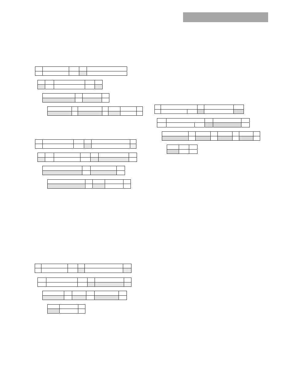
Read input string (DCh) :
Reads back the input voltage and
input power consumed by the power supply. In order to
improve the resolution of the input voltage reading the data
is shifted by 75V.
1 7 1
1
8
S Slave
address Wr A Command
Code
0xDC
1 1
7
1 1
A Sr Slave
Address Rd A
8 1
8
1
Byte Count = 4
A
Voltage A
8 1 8 1
8 1
1
Power - LSB
A Power - MSB A PEC No-ack P
Read_firmware_rev [0 x DD]:
Reads back the firmware
revision of all three µC in the power supply.
1 7 1
1 8 1
S Slave
address Wr A Command
Code
0xDD A
1
1 7 1
1 8 1
A Sr Slave
Address Rd A
Byte Count = 4
A
8 1
8
1
Primary micro revision
A
DSP revision
A
8 1
8
1
1
I2c Micro revision
A
PEC No-ack P
For example; the read returns one byte for each device (i.e.
0 x 002114h ). The sequence is primary micro, DSP, and I
2
C
micro. 0x00 in the first byte indicates that revision
information for the primary micro is not supported. The
number 21 for the DSP indicates revision
2.1, and the
number 14 for the i2c
micro indicates revision 1.4.
Read_run_timer [0 x DE]:
This command reads back the
recorded operational ON state of the power supply in hours.
The operational ON state is accumulated from the time the
power supply is initially programmed at the factory. The
power supply is in the operational ON state both when in
standby and when it delivers main output power. Recorded
capacity is approximately 10 years of operational state.
1 7 1
1
8
1
S Slave
address Wr A Command
Code
0xDE A
1 7 1
1 8 1
Sr Slave
Address
Rd A
Byte count = 4
A
8 1
8
1 8 1
Time - LSB
A
Time
A
Time - MSB
A
8 1
1
PEC No-ack P
Fan_speed_set (DFh) :
This command instructs the power
supply to increase the speed of the fan. The transmitted
data byte represents the hex equivalent of the duty cycle in
percentage, i.e. 100% = 0 x 64h. The command can only
increase fan speed, it cannot instruct the power supply to
reduce the fan speed below what the power supply requires
for internal control.
Fan_normal_speed (E0h):
This command returns fan
control to the power supply. It does not require a trailing
data byte.
Read_Fan_speed (E1h) :
Returns the commanded fan speed
in percent and the measured fan speed in RPM from the
individual fans. Up to 3 fans are supported. If a fan does not
exist (units may contain from 1 to 3 fans), or if the command
is not supported the unit return 0x00.
1
8 1
8 1
S Slave address
Wr
A Command
0xE1 A
1
8
1 8 1
Sr Slave
address Rd A
Byte count = 5
A
8 1
8
1
8
1
8
1
Adjustment %
A Fan-1 A Fan-2 A Fan-3 A
8 1 1
PEC NA P
Stretch_LO_25ms (E2h) :
Command used for production
test of the clock stretch feature.
None supported commands or invalid data:
The power
supply notifies the MASTER if a non-supported command
has been sent or invalid data has been received. Notification
is implemented by setting the appropriate STATUS and
ALARM registers and setting the SMBAlert# flag.
Fault Management
The power supply records faults in the STATUS and ALARM
registers above and notifies the MASTER controller as
described in the Alarm Notification section of the non-
conforming event.
The STATUS and ALARM registers are continuously updated
with the latest event registered by the rectifier monitoring
circuits. A host responding to an SMBusALERT# signal may
receive a different state of the rectifier if the state has
changed from the time the SMBusALERT# has been
triggered by the rectifier.
The power supply differentiates between internal faults
that are within the power supply and external faults that
the power supply protects itself from, such as overload or
input voltage out of limits. The FAULT LED, FAULT PIN or i2c
alarm is not asserted for EXTERNAL FAULTS. Every attempt is
made to annunciate External Faults. Some of these
annunciations can be observed by looking at the input LEDs.
These fault categorizations are predictive in nature and
therefore there is a likelihood that a categorization may not
have been made correctly.
Input voltage out of range:
The Input LED will continue
blinking as long as sufficient power is available to power the
LED. If the input voltage is completely gone the Input LED is
OFF.