Data sheet, Electrical specifications (continued) – GE Industrial Solutions CP2000DC54-PE User Manual
Page 3
GE
Data Sheet
CP2000DC54-PE series dc-dc converter
Input: -40Vdc to -72Vdc; Outputs: ±54Vdc @ 2000W; 5Vdc @ 4W
August 20, 2013
©2013 General Electric Company. All rights reserved.
Page 3
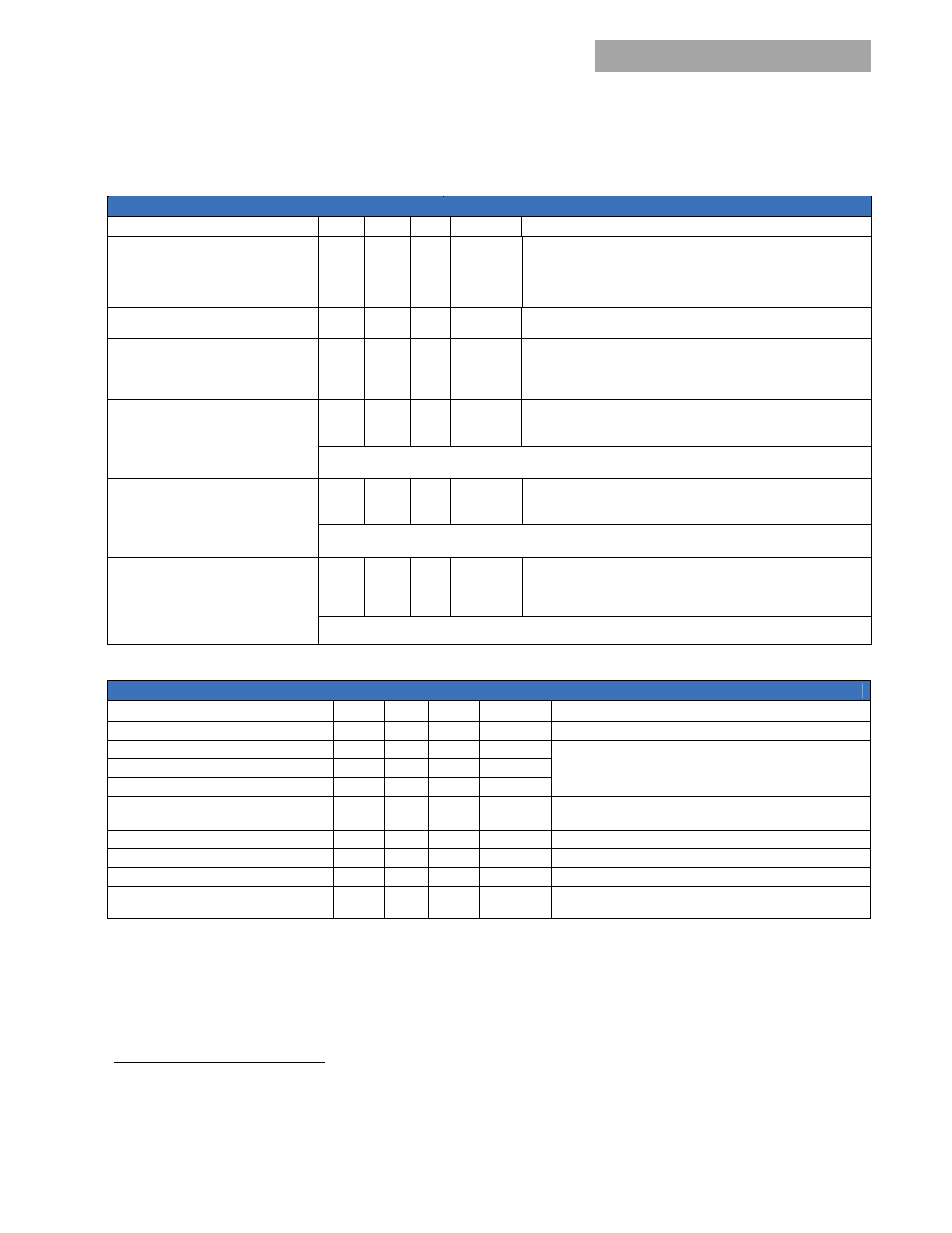
Electrical Specifications (continued)
Output (continued)
Parameter Min
Typ
Max
Units
Notes
Turn-On
Delay
Rise Time
2
Overshoot
5
500
5
s
ms
%
Monotonic Turn_On after detection of valid DC input voltage.
Measured from 30% to 100% of Vnom.
Restart Shutdown Delay
20
S
Shutdown is delayed during a re-start in order to guarantee restart
of multiple paralleled modules.
Load Step Response
I
V
Response Time
2.0
2
50
%FL
Vdc
ms
I/t slew rate 1A/µs.
Settling time to within regulation requirements.
Overload
3
Current Limit
Shutdown
38.9
43
39
Adc
Vdc
Fold-down.
Default state – hiccup mode
System Start-up
A 20 second shutdown delay is implemented to allow modules to be plugged in one at a time. During this time
fold-down occurs but the module will not shut down below 39Vdc.
Over-voltage
Delayed
Instantaneous
Latchoff
60
65
Vdc
Vdc
200msec delayed shutdown implemented.
Latched shutdown without hiccup.
Three restart attempts are implemented within a one minute window prior to a latched shutdown when Vout
< 65Vdc. Beyond 1 minute the counter restarts
Over-temperature
Warning
Shutdown
Auto-recoverable
20
5
°C
°C
Implemented prior to commencement of an OT shutdown
Below the maximum rating of the device being protected
Temperature hysteresis of approximately 10°C provided between shutdown and restart.
Auxiliary Output
Parameter Min
Typ
Max
Units
Notes
ON when the input voltage is
-26
-72
Vdc
Output Voltage Setpoint
5.2
Vdc
Isolated from the main output to meet POE requirements.
50mA dedicated for powering adjacent PEMs during a fault.
700mA available for external use.
Output Current
0.005
0.75
A
Overall Regulation
-5
+5
%
Ripple and Noise
50
100
25
mVpk-pk
mVrms
20MHz bandwidth. Measured across a 1F tantalum and a
0.1F ceramic capacitor
Over-voltage Clamp
7
Vdc
Over-current Limit
110
175
%FL
Isolation from the main output
2250
Vdc
Isolation from frame ground
50
Vdc
A
1MΩ noise suppression resistor is connected between
Logic_GRD and Frame_GRD.
2
Below -5C the rise time is approximately 5 minutes to protect bulk capacitors in the unit
3
Hiccup performance attempts automatic recovery from an overload shutdown with approximately a 90% off-time duty cycle. The duty cycle
varies periodically in order to guarantee multi-module recovery synchronization. Latchoff can be chosen via software instead of the default
hiccup. Recovery from a latchoff requires ENABLING, or software commanding OFF followed by an ON after a 2 second delay.