Data sheet, Pmbus, Commands – GE Industrial Solutions CP2000DC54-PE User Manual
Page 8: Command descriptions
GE
Data Sheet
CP2000DC54-PE series dc-dc converter
Input: -40Vdc to -72Vdc; Outputs: ±54Vdc @ 2000W; 5Vdc @ 4W
August 20, 2013
©2013 General Electric Company. All rights reserved.
Page 8
ensure that only the final state of the power supply is
captured.
Successive read backs:
Successive read backs to the power
supply should not be attempted at intervals faster than
every one second. This time interval is sufficient for the
internal processors to update their data base so that
successive reads provide fresh data.
Device ID:
Address bits A2, A1, A0 set the specific address of
the power supply. The least significant bit x (LSB) of the
address byte configures write [0] or read [1] events. In a
write command the system instructs the power supply. In a
read command information is being accessed from the
power supply.
Address Bit
7 6 5 4 3 2 1 0
PCA9541
1 1 1 0 A2 A1 A0 R/W
Micro
controller
1 0 0 0 A2 A1 A0 R/W
External
EEPROM
1 0 1 0 A2 A1 A0 R/W
Global
Broadcast 0 0 0 0 0 0 0 0
MSB
LSB
The Global Broadcast instruction executes a simultaneous
write instruction to all power supplies. A read instruction
cannot be accessed globally. The three programmable
address bits are the same for all I
2
C accessible devices
within the power supply.
PMBus
TM
Commands
Standard instruction:
Up to two bytes of data may follow
an instruction depending on the required data content.
Analog data is always transmitted as LSB followed by MSB.
PEC is mandatory and includes the address and data fields.
1 8 1
8 1
S Slave
address Wr A Command
Code A
8 1 8 1
8
1
1
Low data byte
A High
data
byte A PEC A P
Master to Slave Slave to Master
SMBUS annotations; S – Start , Wr – Write, Sr – re-Start, Rd –
Read,
A – Acknowledge, NA – not-acknowledged, P – Stop
Direct mode data format:
The Direct Mode data format is
supported, where y = [ mX + b ] x 10
R
. In the equation, y is
the data value from the controller and x is the ‘real’ value
either being set or returned.
For example, to set the output voltage to 50.45V
DC
, Multiply
the desired set point by the m constant, 50.45 x 400 =
20,180. Convert this binary number to its hex equivalent:
20,180b = 0x4ED4. The result is sent LSB=0xD4 first, then
MSB=0x4E.
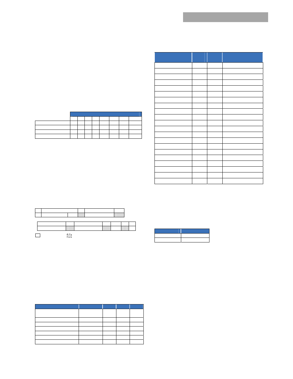
The constants are
FUNCTION
Operation
m
b
R
Output voltage
Output voltage shutdown
Write / read
400
0
0
Output Current
read
5
0
0
Temperature
read
1
0
0
Input Voltage
read
1
75
0
Input Power
read
1
0
0
Fan Speed setting ( % )
read
1
0
0
Fan speed in RPM
read
100
0
0
PMBus
TM
Command set:
Command
Hex
Code
Data
Field
Function
Operation 01
1
Output
ON/OFF
Clear_Faults 03
0
Clear
Status
Vout_command 21
2
Set
Vout
Vout_OV_fault_limit
40
2
Set OV fault limit
Read_status
D0
10
Read Status, V
out
, I
out
, T
LEDs test ON
D2
0
Test LEDs
LEDs test OFF
D3
0
Service_LED_ON D4
0
Service
LED
Service_LED_OFF D5 0
Enable_write
D6
0
Enable EEPROM write
Disable_write D7
0
Disable
EEPROM
write
Inhibit_restart D8
0
Latch
upon
failure
Auto_restart D9
0
Hiccup
Isolation_test DA
0
Perform
isolation
test
Read_input_string
DC
2
Read Vin and Pin
Read_firmware_rev DD 3 Firmware
revisions
Read_run_timer DE
3
Accumulated
ON
state
Fan_speed_set
DF
3
Fan speed control
Fan_normal_speed E0 0
Stop
fan
control
Read_fan_speed
E1
4
Fan control & speed
Stretch_LO_25ms
E2
0
Production test feature
Command Descriptions
Operation (01h) :
By default the Power supply is turned ON
at power up as long as ENABLE is active LO. The Operation
command is used to turn the Power Supply ON or OFF via
the PMBus. The data byte below follows the OPERATION
command.
FUNCTION
DATA BYTE
Unit ON
0x80
Unit OFF
0x00
To RESET the power supply cycle the power supply OFF, wait
at least 2 seconds, and then turn back ON. All alarms and
shutdowns are cleared during a restart.
Clear_faults (03h):
This command clears information bits in
the STATUS registers, these include:
Isolation OK
Isolation test failed
Restarted OK
Invalid command
Invalid data
PEC error
Vout_Command (21h) :
This command is used to change
the output voltage of the power supply. Changing the output
voltage should be performed simultaneously to all power
supplies operating in parallel using the Global Address
(Broadcast) feature. If only a single power supply is
instructed to change its output, it may attempt to source all
the required power which can cause either a power limit or
shutdown condition.