Data sheet, P1 a6 p7 a1, Alarm table – GE Industrial Solutions CP2000DC54-PE User Manual
Page 13: Output connector
GE
Data Sheet
CP2000DC54-PE series dc-dc converter
Input: -40Vdc to -72Vdc; Outputs: ±54Vdc @ 2000W; 5Vdc @ 4W
August 20, 2013
©2012 General Electric Company. All rights reserved.
Page 13
Alarm Table
Power Supply LED State
Monitoring Signals
(Referenced to Logic_GRD)
Condition
IN OK
Green
DC OK
Green
Service
Amber
Fault
Red
Fault OTW
Power
OK
I_Limit
Module
Present
OK 1
1
0
0
HI HI HI
HI LO
Thermal Alarm
(5C before shutdown)
1 1 1 0
HI LO HI
HI
LO
Thermal Shutdown
1
0
1
1
LO LO LO
HI LO
Defective Fan
1
0
0
1
LO HI LO
HI LO
Blown Input Fuse in Unit
1
0
0
1
LO HI LO
HI
LO
No Input > 8mS (single unit)
0
1
0
0
HI HI LO
2
HI LO
Input Present but not within limits
0
0
0
0
HI HI LO HI LO
Input not present (with back bias)
0
0
0
0
HI HI LO HI LO
Over Voltage Latched Shutdown
1
0
0
1
LO HI LO
HI LO
Over Current
1
Blinks
0
0
HI HI LO LO LO
Over Current Shutdown
1
0
0
0
HI HI LO LO LO
Non-catastrophic Internal Failure
1
1
1
0
1
LO HI HI
HI
LO
1 Missing Module (external pull-up)
HI
Standby (remote)
1
0
0
0
HI HI LO HI LO
Service Request (i
2
C mode)
1
1
Blinks
0
HI HI HI
HI LO
1
Any detectable fault condition that does not result in the power supply shutting down. For example, ORing FET failure, boost section out of
regulation, etc.
2
Signal transition from HI to LO is output load dependent
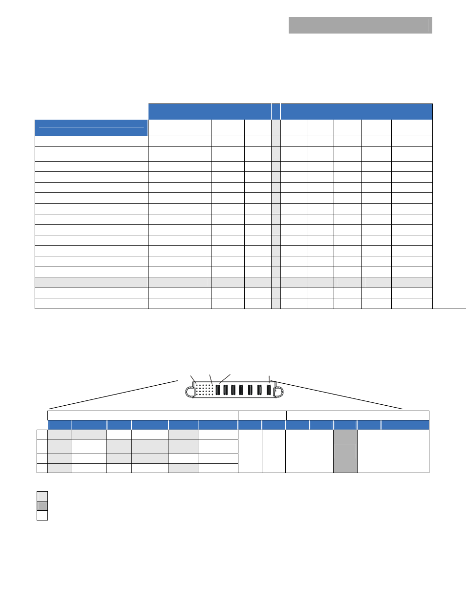
Output Connector
Mating Connector: AMP 1450572-1
P1
A6
P7
A1
Signal Output
Power
Input
Power
6
5
4
3
2
1
P7
P6
P5
P4
P3
P2
P1
A SCL_0 MOD_PRES Ilimit
LOGIC_GRD RS 485+
UNIT_ADDR
V_OUT
(-DC)
V_OUT
(+DC)
CO_RTN
Vin ( + )
EARTH
(GND)
CO_LINE
Vin ( - )
B SCL_1 OTW Alert#_
0
Alert#_1
RS 485-
8V_INT
C SDA_0 Margin Enable
Reset Ishare N/C
D SDA_1 Fault 5VA
Power_OK
ON/OFF SHELF_ADDR
Connector is viewed from the rear positioned inside the power supply.
Signal pins columns 1 and 2 are referenced to V_OUT (-DC). Signal pins columns 3 through 6 are referenced to Logic GRD.
Last-to-make first-to-break pins.
First-to-make last-to-break longest pin implemented in the mating connector.
N/C – no connect pins must be left open. Do not connect these pins to either voltage sources or ground.