Data sheet – GE Industrial Solutions CP2000DC54-PE User Manual
Page 10
GE
Data Sheet
CP2000DC54-PE series dc-dc converter
Input: -40Vdc to -72Vdc; Outputs: ±54Vdc @ 2000W; 5Vdc @ 4W
August 20, 2013
©2013 General Electric Company. All rights reserved.
Page 10
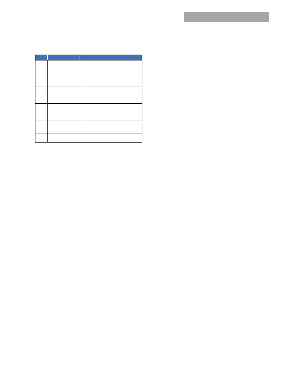
Alarm-1
Bit
Title
Description
7
Unit in power limit
An overload condition that results in
constant power
6
Primary fault
Indicates either primary failure or
INPUT not present. Used in
conjunction with bit-0 and Status_1
bits 2 and 5 to assess the fault.
5 Over
temp.
shutdown
One of the over_temperature
sensors tripped the supply
4
Over temp warning
Temperature is too high, close to
shutdown
3
In over current
Shutdown is triggered by low
output voltage < 39V
DC
.
2 Over
voltage
shutdown
1
Vout out_of_limits
Indication the output is not within
design limits. This condition may or
may not cause an output shutdown.
0
Vin out_of_limits
The input voltage is outside design
limits
LEDS test ON (D2h) :
Will turn-ON simultaneously the four
front panel LEDs of the Power supply sequentially 7 seconds
ON and 2 seconds OFF until instructed to turn OFF. The
intent of this function is to provide visual identification of the
power supply being talked to and also to visually verify that
the LEDs operate and driven properly by the micro
controller
.
LEDS test OFF (D3h) :
Will turn-OFF simultaneously the four
front panel LEDs of the Power supply.
Service LED ON (D4h) :
Requests the power supply to flash-
ON the Service (ok-to-remove) LED. The flash sequence is
approximately 0.5 seconds ON and 0.5 seconds OFF.
Service LED OFF (D5h) :
Requests the power supply to turn
OFF the Service (ok-to-remove) LED.
Enable write (D6h) :
This command enables write
permissions into the upper ¼ of memory locations for the
external EEPROM. A write into these locations is normally
disabled until commanded through I
2
C to permit writing into
the protected area. A delay of about 10ms is required from
the time the instruction is requested to the time that the
power supply actually completes the instruction.
See the FRU-ID section for further information of content
written into the EEPROM at the factory.
Disable write (D7h) :
This command disables write
permissions into the upper ¼ of memory locations for the
external EEPROM.
Unit in Power Limit or in Current Limit:
When output
voltage is > 36V
DC
the Output LED will continue blinking.
When output voltage is < 36V
DC
, if the unit is in the RESTART
mode, it goes into a hiccup. When the unit is ON the output
LED is ON, when the unit is OFF the output LED is OFF.
When the unit is in latched shutdown the output LED is
OFF.
Inhibit_restart (D8h) :
The Inhibit-restart command directs
the power supply to remain latched off for over_voltage,
over_temperature and over_current. The command needs
to be sent to the power supply only once. The power supply
will remember the INHIBIT instruction as long as internal
bias is active.
Restart after a lachoff:
To restart after a latch_off either of
four restart mechanisms are available. The hardware pin
Enable may be turned OFF and then ON. The unit may be
commanded to restart via i2c through the Operation
command by first turning OFF then turning ON . The third
way to restart is to remove and reinsert the unit. The fourth
way is to turn OFF and then turn ON ac power to the unit.
The fifth way is by changing firmware from latch off to
restart. Each of these commands must keep the power
supply in the OFF state for at least 2 seconds, with the
exception of changing to restart.
A successful restart shall clear all alarm registers, set the
restarted successful bit of the Status_2 register.
A power system that is comprised of a number of power
supplies could have difficulty restarting after a shutdown
event because of the non-synchronized behavior of the
individual power supplies. Implementing the latch-off
mechanism permits a synchronized restart that guarantees
the simultaneous restart of the entire system.
A synchronous restart can be implemented by;
1. Issuing a GLOBAL OFF and then ON command to all
power supplies,
2. Toggling Off and then ON the ENABLE signal
3. Removing and reapplying input commercial power to the
entire system.
The power supplies should be turned OFF for at least 20 – 30
seconds in order to discharge all internal bias supplies and
reset the soft start circuitry of the individual power supplies.
Auto_restart (D9h) :
Auto-restart is the default
configuration for overvoltage, overcurrent and
overtemperature shutdowns.
However, overvoltage has a unique limitation. An
overvoltage shutdown is followed by three attempted
restarts, each restart delayed 1 second, within a 1 minute
window. If within the 1 minute window three attempted
restarts failed, the unit will latch OFF. If within the 1 minute
less than 3 shutdowns occurred then the count for latch OFF
resets and the 1 minute window starts all over again.
This command resets the power supply into the default
auto-restart configuration.
Isolation test (DAh):
This command verifies functioning of
output OR’ing. At least two paralleled power supplies are
required. The host should verify that N+1 redundancy is
established. If N+1 redundancy is not established the test
can fail. Only one power supply should be tested at a time.
Verifying test completion should be delayed for
approximately 30 seconds to allow the power supply
sufficient time to properly execute the test.
Failure of the isolation test is not considered a power supply
FAULT because the N+1 redundancy requirement cannot be
verified. The user must determine whether a true isolation
fault indeed exists.