Connecting the hardware, Antenna connector, Power connector – B&B Electronics ESR901WB - Manual User Manual
Page 19
Hardware
Overview
Manual Documentation Number: ESR901WB-2907m
pn6870-rev002
B&B Electronics Mfg Co Inc – 707 Dayton Rd - PO Box 1040 - Ottawa IL 61350 - Ph 815-433-5100 - Fax 815-433-5104 – www.bb-elec.com
B&B Electronics Ltd – Westlink Commercial Park – Oranmore, Galway, Ireland – Ph +353 91-792444 – Fax +353 91-792445 – www.bb-europe.com
Chapter 2
9
• Press for at least 1 second, release in less than 10 seconds:
reset serial server operating system
• Press and hold 10+ seconds(during power-up): reset serial
server to factory default settings.
Antenna Connector
The antenna connector is a reverse SMA connector.
An omni-directional antenna is supplied with ESR901WB
wireless serial servers. All ESR901WB serial servers are FCC-
certified when the supplied antenna is used.
Power Connector
The power connector is a removable terminal block with two screw
terminals. The top terminal is negative (-) power supply. The
bottom terminal is positive (+) power supply. The power supply
voltage range is 10 VDC to 30 VDC.
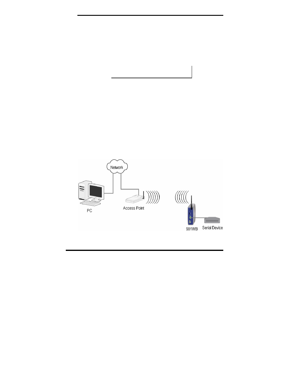
Connecting the Hardware
A typical connection for the ESR901WB Wireless Serial Server is
infrastructure mode operation, in which the ESR901WB
communicates with a PC on a wired network via an access point,
which is often a wireless switch or router.
Figure 2.
Connection via the Wireless LAN