Max3746, Design procedure, Power detect and loss-of-signal indicator – Rainbow Electronics MAX3746 User Manual
Page 8: Program the los assert threshold
MAX3746
Power Detect and Loss-of-Signal Indicator
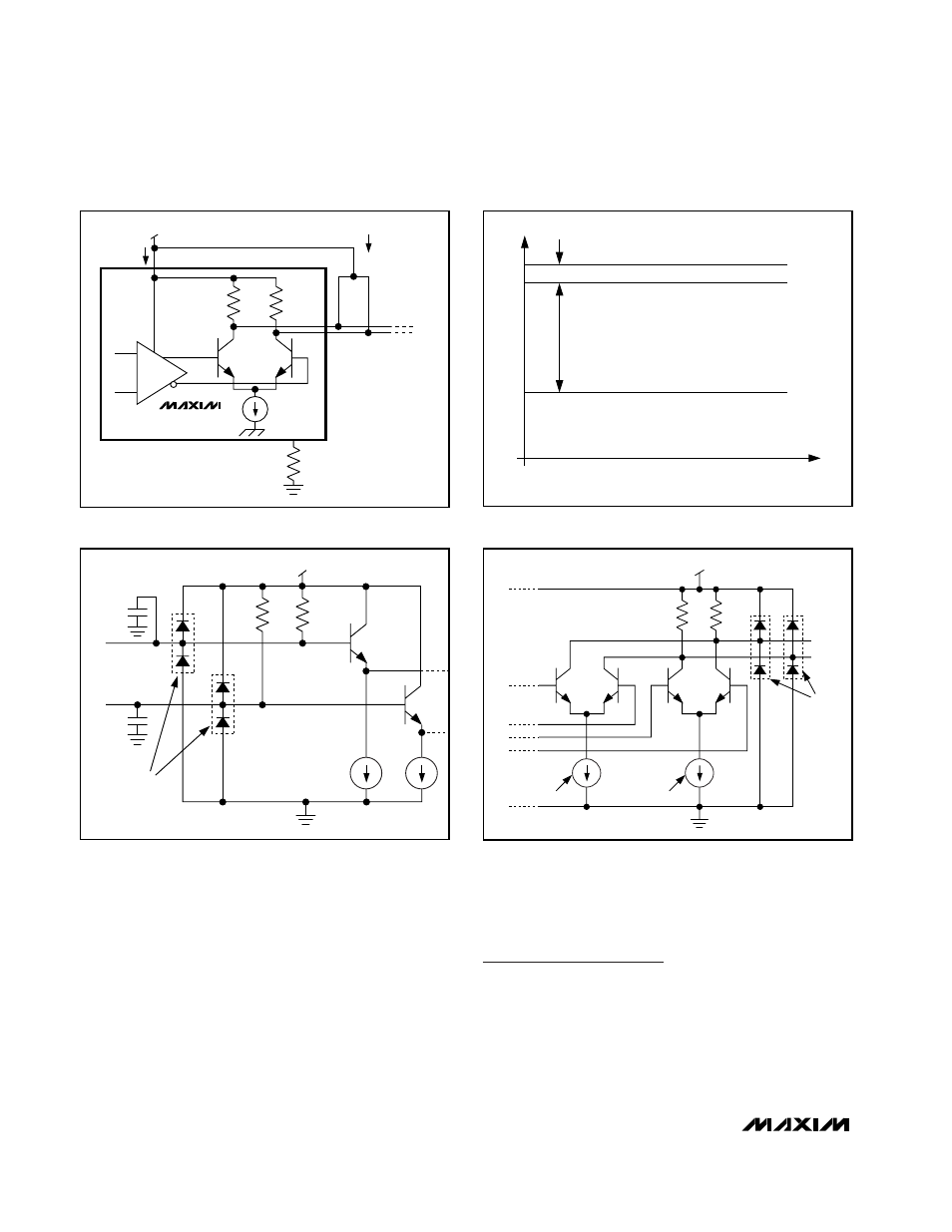
The MAX3746 is equipped with multirate LOS circuitry
that indicates when the input signal is below a pro-
grammable threshold, set by resistor R
TH
at the TH pin
(see the Typical Operating Characteristics for appropri-
ate resistor sizing). An averaging RMS power detector
compares the input signal amplitude with this threshold
and feeds the signal-detect information to the open-col-
lector LOS output.
To prevent LOS chatter in the region of the pro-
grammed threshold, approximately 2dB of hysteresis is
built into the LOS assert/deassert function. Once
asserted, the LOS is not deasserted until the input
amplitude rises to the required level (V
DEASSERT
). (See
Figures 2 and 5.)
Design Procedure
Program the LOS Assert Threshold
External resistor, R
TH,
programs the loss-of-signal
threshold. See the LOS Threshold vs. R
TH
graph in the
Typical Operating Characteristics to select the appro-
priate resistor.
Low-Power, 622Mbps to 3.2Gbps
Limiting Amplifier
8
_______________________________________________________________________________________
V
CC
I
CC
(SUPPLY CURRENT)
I
OUT
(CML
OUTPUT CURRENT)
50Ω
R
TH
50Ω
MAX3746
Figure 1. Power-Supply Current Measurement
1dB
6dB
0V
SIGNAL ON
MAX DEASSERT LEVEL
MIN ASSERT LEVEL
POWER-DETECT WINDOW
V
IN
TIME
SIGNAL OFF
Figure 2. LOS Assert Threshold Set 1dB Below the Minimum by
Receiver Sensitivity for Selected R
TH
50Ω
50Ω
IN+
IN-
0.25pF
0.25pF
V
CC
ESD
STRUCTURES
Figure 3. CML Input Buffer
Q3
Q4
Q1
V
CC
50Ω
50Ω
Q2
I2 = f (OUTPOL, DISABLE)
I1 = f (OUTPOL, DISABLE)
DISABLE
DATA
OUT+
OUT-
ESD
STRUCTURES
Figure 4. CML Output Buffer