Absolute maximum ratings, Electrical characteristics – Rainbow Electronics MAX3746 User Manual
Page 2
MAX3746
Low-Power, 622Mbps to 3.2Gbps
Limiting Amplifier
2
_______________________________________________________________________________________
ABSOLUTE MAXIMUM RATINGS
Stresses beyond those listed under “Absolute Maximum Ratings” may cause permanent damage to the device. These are stress ratings only, and functional
operation of the device at these or any other conditions beyond those indicated in the operational sections of the specifications is not implied. Exposure to
absolute maximum rating conditions for extended periods may affect device reliability.
Power-Supply Voltage (V
CC
) .................................-0.5V to +4.5V
Voltage at IN+, IN- ..........................(V
CC
- 2.4V) to (V
CC
+ 0.5V)
Voltage at DISABLE, OUTPOL, RSSI,
LOS, TH ...................................................-0.5V to (V
CC
+ 0.5V)
Current into LOS.....................................................1mA to +9mA
Differential Input Voltage (IN+ - IN-) .....................................2.5V
Continuous Current at CML Outputs
(OUT+, OUT-) ................................................-25mA to +25mA
Continuous Power Dissipation (T
A
= + 70°C)
16-Pin QFN (derate 17.7mW above +70°C) .....................1.4W
Operating Junction Temperature Range (T
J
) ....-55°C to +150°C
Storage Ambient Temperature Range (Ts) .......-55°C to +150°C
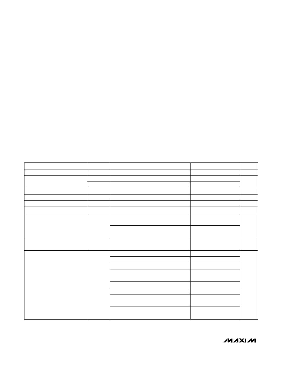
ELECTRICAL CHARACTERISTICS
(V
CC
= +2.97V to +3.63V, CML output load is 50Ω to V
CC
, T
A
= -40°C to +85°C, unless otherwise noted. Typical values are at V
CC
=
+3.3V, T
A
= +25°C, unless otherwise specified. The data input transition time is controlled by 4th-order Bessel filter with f
-3dB
= 0.75 x
2.667GHz for all data rates of 2.667Gbps and below, and with f
-3dB
= 0.75 x 3.2GHz for a data rate of 3.2Gbps.)
PARAMETER
SYMBOL
CONDITIONS
MIN
TYP
MAX
UNITS
Single-Ended Input Resistance
R
IN
Single ended to V
CC
42
50
58
Ω
se S
11
S i ng l e end ed , f < 3GH z, D U T i s p ow er ed on
14
Input Return Loss
diff S
11
Differential, f < 3GHz, DUT is powered on
15
dB
Input Sensitivity
V
IN-MIN
(Note 1)
2
4
mV
P-P
Input Overload
V
IN-MAX
(Note 1)
1200
mV
P-P
Single-Ended Output Resistance
R
OUT
Single ended to V
CC
42
50
58
Ω
Output Return Loss
diff S
22
Differential, f < 3GHz, DUT is powered on
20
dB
4mV
P-P
<
V
IN
<
1200mV
P-P
,
OUTPOL connected to V
CC
or GND
600
800
1000
CML Differential Output Voltage
4mV
P-P
<
V
IN
<
1200mV
P-P
,
OUTPOL open or connected to 30k
Ω
400
500
600
mV
P-P
Differential Output Signal when
Disabled
Outputs AC-coupled,
V
IN-MAX
applied to input (Note 2)
10
mV
P-P
K28.5 pattern at 3.2Gbps (Note 2)
8.4
18
K28.5 pattern at 3.2Gbps at T
A
= +100
°
C
10.2
2
23
- 1 PRBS equivalent at 2.7Gbps (Note 2)
11.6
23
2
23
- 1 PRBS equivalent pattern at 2.7Gbps
at T
A
= +100
°
C
13.1
K28.5 pattern at 2.1Gbps
8
20
K28.5 pattern at 2.1Gbps at T
A
= +100
°
C
9.7
2
23
- 1 PRBS equivalent pattern at 622Mbps
(Note 2)
42.5
69
Deterministic Jitter
(Note 3)
DJ
2
23
- 1 PRBS equivalent pattern at 622Mbps
at T
A
= +100
°
C
47.8
ps
P-P