Rainbow Electronics AT73C502 User Manual
Page 20
AT73C500
20
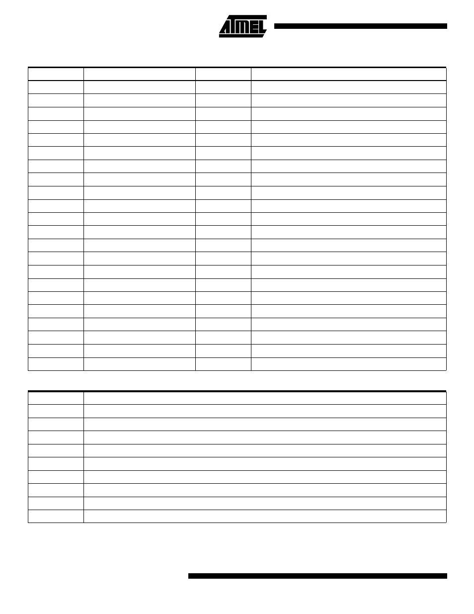
The calibration data is transferred in the following sequence:
The meaning of the calibration coefficient mnemonics are as follows:
Byte
Calibration Coefficient
Byte
Calibration Coefficient
0
PC1
1
PC1 back-up
2
PC2
3
PC2 back-up
4
PC3
5
PC3 back-up
6
MCC
7
MCC back-up
8
Not used
9
Not used
10
AGC1
11
AGC1 back-up
12
AGC2
13
AGC2 back-up
14
AGC3
15
AGC3 back-up
16
RGC1
17
RGC1 back-up
18
RGC2
19
RGC2 back-up
20
RGC3
21
RGC3 back-up
22
UGC1
23
UGC1 back-up
24
UGC2
25
UGC2 back-up
26
UGC3
27
UGC3 back-up
28
STUPC
29
STUPC back-up
30
AOF1
31
AOF1 back-up
32
AOF2
33
AOF2 back-up
34
AOF3
35
AOF3 back-up
36
ROF1
37
ROF1 back-up
38
ROF2
39
ROF2 back-up
40
ROF3
41
ROF3 back-up
42
OFFMOD
43
OFFMOD back-up
Mnemonic
Meaning
PC
N
Phase calibration factor, phase N
MCC
Display pulse adjustment factor for active and reactive energy
AGC
N
Gain calibration factor for active power and energy calculation, phase N
RGC
N
Gain calibration factor for reactive power and energy calculation, phase N
UGC
N
Gain calibration factor for phase voltage, phase N
STUPC
Starting current adjustment factor
AOF
N
Offset calibration factor for active power and energy calculation, phase N
ROF
N
Offset calibration factor for reactive power and energy calculation, phase N
OFFMOD
Controls the use of offset factors