Rainbow Electronics AT73C502 User Manual
Page 16
AT73C500
16
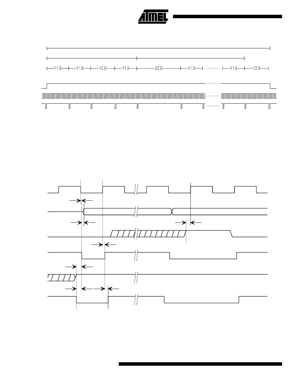
Figure 11. Contents of a data package
AT73C500 offers some time for the processor to analyze
the synchronization, status and mode information before
starting to supply the measurement results. The 12 mea-
surement bytes are written on every 11th clock period.
Four handshake signals are provided, ADDR1, RD/WR,
STROBE and BRDY, for interfacing with the microproces-
sor. ADDR1 is always taken high when AT73C500 is either
writing to µP bus or reading the bus contents. When used
with slow peripheral, the BRDY input of AT73C500 can be
used to hold the device in write mode until the processor
has finished reading the bus. However, the total length of
one data package should always be less than 300 clock
cycles of AT73C500. Longer I/O periods may result errone-
ous measurement results.
Figure 12. Handshake signals of the DSP
Following the falling edge of BRDY, the data can be
strobed into the µP by the rising edge of the STROBE sig-
nal. If the microprocessor is able to read data continuously,
BRDY can be kept constantly low. Also BRDY should be
low whenever DATRDY is inactive allowing AT73C500
freely use its buses.
To avoid conflicts, the processor should always keep its
bus in tri-state mode, unless it is used to write calibration
coefficients to AT73C500.
Sync LS
Sync MS
Mode
Status
Data 1
Data 2
Data 11
Measurement data, 12 bytes
Synchronisation data
Status data
Data 12
200 clock cycles
45 clock cycles
143 clock cycles
LATCHED
DATRDY
CLK
STROBE
RWSU
ASU
RWH
SH
BRS
CLK
DATA
FROM DSP
BRDY
STROBE
ADDR1
RD/WR
SDLY
DDLY