At93c46, At90sxx – Rainbow Electronics AT73C502 User Manual
Page 2
AT73C500
2
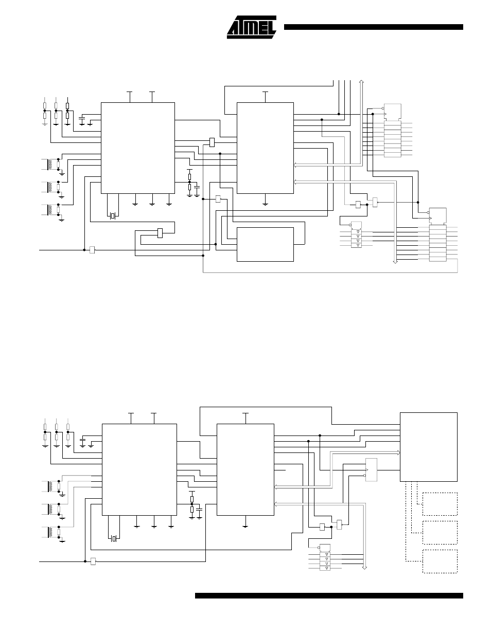
Figure 1. Block diagram of the AT73C500 chipset in stand-alone configuration
The AT73C500 is programmed to measure active, reactive
and apparent phase powers. Phase factors, phase volt-
ages, phase currents and line frequency are also mea-
sured, simultaneously. Based on the individual phase
powers, total active power is determined.
The power values are calculated over one-line frequency
cycle. The negative and positive results are accumulated in
different registers, which allows for separate billing of
imported and exported active energy. Also, the reactive
results are sorted depending on whether capacitive or
inductive load is applied.
Eight pulse outputs are provided. Each billing quantity
(+Wh, -Wh, +VArh, -Varh) is supplied with its own meter
constant output, as well as a display counter output. In
multi-channel mode, AT73C500 performs the functions of
three independent single phase Wh meters and three
impulse outputs are available, one for each meter element.
All measurement information is available on an 8-bit micro-
processor bus. The results are output in six packages, 16
bytes each. Mode and status information of the meter is
also transferred with each data block.
Figure 2. Block diagram of the AT73C500 chipset in microprocessor configuration
AT73C500
DEDICATED DSP
FOR ENERGY
METERING
STROBE
RD/WR
ADDR1
ADDR0
IRQ0
IRQ1
SIN
SCLK
SOUT1
SOUT0
DATA BUS
STATUS BUS
XRES
VCC
GND
DGND
BRDY
1
1
1
1
TAMP
STUP
L3
L2
L1
FAIL
DATRDY
INI
1
&
AT93C46
EEPROM
128*8 bit
CS
SK
DI
DO
AT73C501
SIX SINGLE-ENDED,
INDEPENDENT
SIGMA-DELTA
CONVERTERS
AIN2
AIN4
AIN6
AIN1
AIN3
AIN5
XI
XO
MODE
VSA
VSSA
VDA
VDDA
VCC
AGND
GND
VGND
VREF
BGD
RESET
CS
PFAIL
ACK
DATA
CLKR
CLK
L1 L2 L3
L1
L2
L3
-VArh
+VArh
-Wh
+Wh
+Wh
-Wh
+VArh
-VArh
MODE2
MODE1
MODE0
RESET
EXTERNAL CONNECTOR
1
&
1
&
CLK
D
AT73500
DEDICATED DSP
FOR ENERGY
METERING
STROBE
RD/WR
ADDR1
ADDR0
IRQ0
IRQ1
SIN
SCLK
SOUT1
SOUT0
DATA BUS
STATUS BUS
XRES
VCC
BRDY
1
1
1
1
1
AT73501
SIX SINGLE-ENDED,
INDEPENDENT
SIGMA-DELTA
CONVERTERS
AIN2
AIN4
AIN6
AIN1
AIN3
AIN5
XI
XO
MODE
VSA
VSSA
VDA
VDDA
VCC
AGND
VREF
BGD
RESET
CS
PFAIL
ACK
DATA
CLKR
CLK
L1 L2 L3
L1
L2
L3
MODE2
MODE1
MODE0
RESET
1
&
B14
B13
B12
B9
DATRDY
AT90Sxx
MICROCONTROLLER
MODEM
LCD
EEPROM
GND
VGND
GND
DGND