Status information – Rainbow Electronics AT73C502 User Manual
Page 17
AT73C500
17
Status Information
AT73C500 provides the following status information
through the Status bus of AT73C500 (B8 - B15, ADDR0).
High level of Lx flags indicates that a phase voltage is
above 10% level of the full scale voltage. If a voltage drop
is detected, the corresponding status bit is written low.
AT73C500 is continuously monitoring the voltage of each
phase.
FAIL flag signifies that something abnormal has been
detected. The following situations may cause a high level of
FAIL: read operation of calibration coefficients is not suc-
cessful, the serial bus of AT73C501 or AT73C502 is not
working properly, the measurement results can’t be trans-
ferred to microprocessor, AT73C500 has detected an inter-
nal failure.
If any of the calibration coefficients and corresponding
back-up values do not match, AT73C500 performs two
extra read operations to eliminate the possibility of a trans-
fer error. If the error still exists after the third trial, incorrect
coefficients are replaced by the default values. FAIL flag is
activated indicating that a potential error has been
detected. FAIL is also taken high in case it is not possible
to read calibration coefficients from the µP or EEPROM, or
if the processor supplies too few coefficients. In both cases,
the read operation will finish in a time-out situation.
The voltage monitoring block of AT73C501/AT73C502 is
used to detect voltage interruptions before the supply volt-
age of AT73C500 drops. High level of PFAIL output at the
ADC indicates a voltage break situation. The measurement
results supplied by AT73C501/AT73C502 may be errone-
ous, and AT73C500 and microprocessor has to be pre-
pared for supply voltage interruption. A high level of PFAIL
causes an immediate write of data packages 3 and 4
(accumulated energy information) to processor bus. The
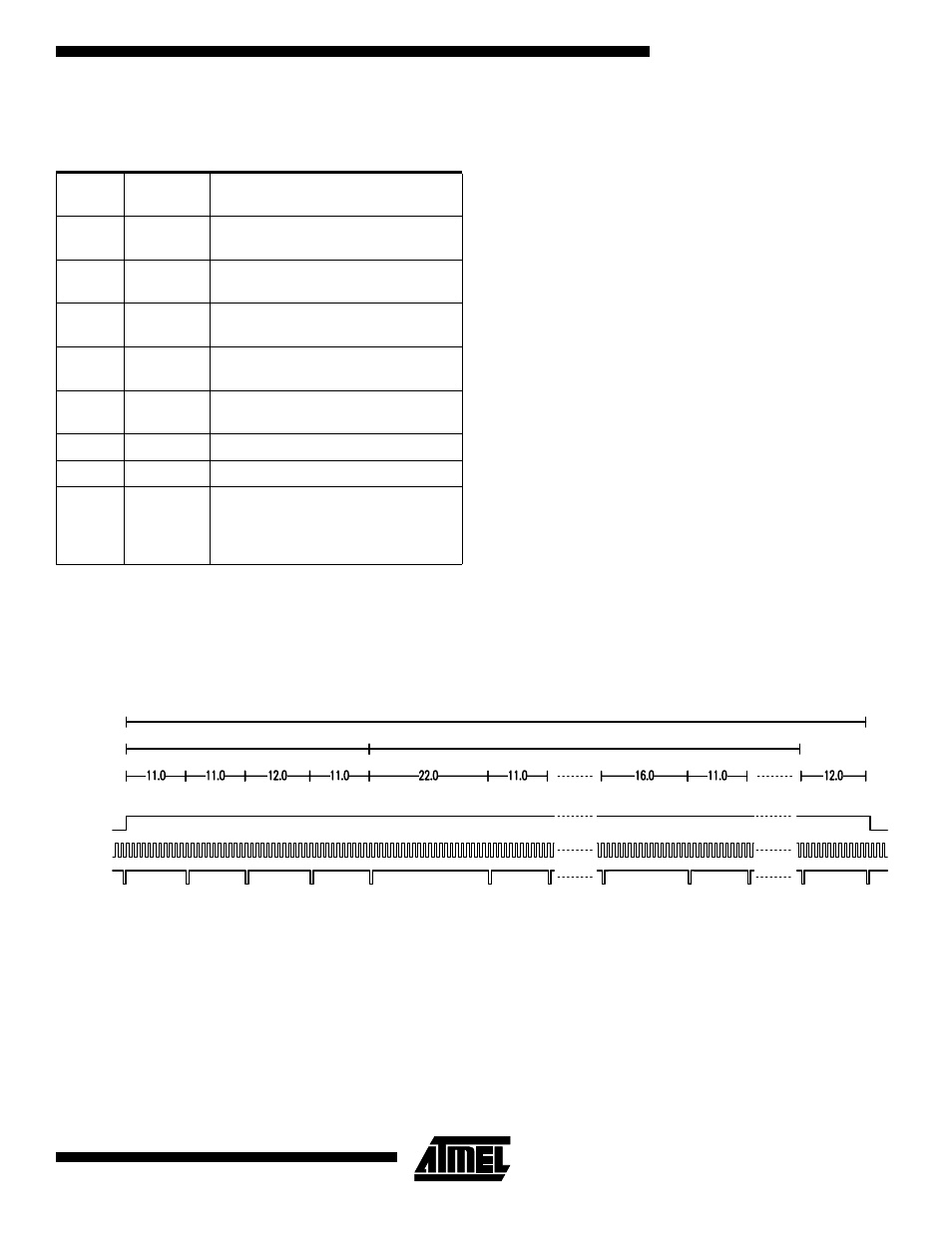
timing of this operation is presented in Figure 13. There are
16 clocks between the two 12 byte data packages but the
header bytes are not repeated in the beginning of package
4.
Figure 13. Transfer of billing information to processor following a PFAIL interrupt
In case of an imminent voltage break, the microprocessor
stores the energy values into a non-volatile memory. The
devices can operate for a short period of time powered by
an electrolytic capacitor or by battery back-up.
AT73C500 devices are taken to a soft reset state and nor-
mal operation will be recovered after the supply voltage is
high again. About one line cycle is needed to start normal
measurements. During this initialization phase no calcula-
tions are performed.
STUP output (active high) indicates that the current of each
of the three phases is below the specified starting level and
no energy is accumulated. This status flag is very useful
during the calibration of a meter since immediate feedback
about staring current level is provided.
TAMP flag informs about potential tampering. It is activated
if one or more phase currents are zero or negative. There-
fore it very effectively indicates current transformer reversal
or short-circuit.
Status
Bus Bit
Status
Flag
Meaning
B15
TAMP
High: Potential event of
tampering detected
B14
STUP
High: Current of all phases
below starting level
B13
L3
High: Phase 1 voltage above
10% of full-scale
B12
L2
High: Phase 2 voltage above
10% of full-scale
B11
L1
High: Phase 3 voltage above
10% of full-scale
B10
FAIL
High: Operating error detected
B9
DATRDY
High: Data available on the µP bus
B8
INI
Low: AT73C500 in initialization
phase, EEPROM interface in use,
AT73C501 (or AT73C502) interface
disabled
Sync LS
Sync MS
Mode
Status
Data 1
Data 2
Data 12
Measurement data, 12 bytes + 12 bytes
Synchronisation data
Status data
Data 1
337 clock cycles
45 clock cycles
280 clock cycles
Data 12
Data 2
LATCHED
DATDRY
CLK
STROBE