Impulse outputs, Multi-channel mode, Test mode – Rainbow Electronics AT73C502 User Manual
Page 18
AT73C500
18
Impulse Outputs
AT73C500 provides eight impulse outputs, four meter con-
stant outputs and four pulse outputs to drive electrome-
chanical display counters which can register exported and
imported active energy and capacitive and inductive reac-
tive energy. These outputs use the same output lines as
used for the processor interface. Impulses are combined
with address 0 (ADDR0). The table below shows the
impulse outputs available in modes 1 and 3. Mode 7 offers
the same outputs, but the rate of the display pulses is
10imp/kWh (kVArh).
An external register is needed to latch and buffer the
pulses. The register can further drive both electromechani-
cal display counters and LEDs. In modes 1 to 4, the nomi-
nal pulse rate of display outputs is 100imp/kWh or
100imp/kVArh (U
MAX
= 270V, I
MAX
= 80A) and meter con-
stant outputs 1250imp/kWh (1250imp/kVArh). The length
of each display pulse is 117ms when operated from
3.2678 MHz crystal. Meter constant pulse stays high for 20
ms.
If the devices are used in a 5A meter, current inputs can be
scaled to 8A full scale level. In this case, the nominal
impulse rates are ten times higher than the above values.
Multi-channel Mode
Modes 2 and 4 are reserved for multi-channel operation. In
these modes, the chips operate like three independent sin-
gle phase meters and store the calculation results in sepa-
rate registers phase-by-phase (meter-by-meter). The basic
sequence of operation is otherwise similar to the normal
mode.
Impulse Outputs
In multichannel operation three impulse outputs are avail-
able for display counters. The absolute energy value is
measured and the reversal of current flow doesn’t affect to
pulse rates. The FAIL signal can, however, be used to
determine whether the energy being registered is positive
or negative. Meter constant pulse rate corresponds to total
active energy of the three single phase channels summed
together as shown in the table below.
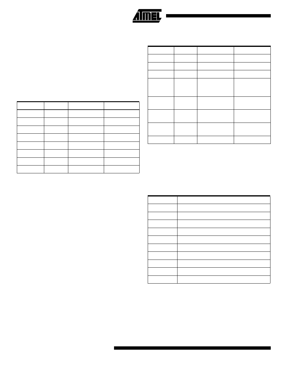
Test Mode
This mode can be used for initial calibration purposes or in
a special meter for additional processing of sample data. In
this mode, AT73C501/AT73C502 samples the six inputs
normally and transfers the samples to AT73C500, which
performs DC suppression and further writes the samples to
8-bit processor bus together with header bytes in the fol-
lowing sequence.
Several input combinations can be measured to check the
gain and phase error in different conditions. An interfacing
computer can be programmed to calculate the calibration
coefficients based on the samples supplied by AT73C500.
At the end of the calibration, the coefficients have to be
stored in a non-volatile memory of the meter as described
in “Loading of Calibration Coefficients” on page 19.
Table 8. Impulse Outputs in Operating Modes 1 and 3
Output Bit
Impulse
Output Type
Impulse Rate
B7
- VArh
Meter Constant
1250imp/kVArh
B6
+ VArh
Meter Constant
1250imp/kVArh
B5
- Wh
Meter Constant
1250imp/kWh
B4
+ Wh
Meter Constant
1250imp/kWh
B3
+ Wh
Display
100imp/kWh
B2
- Wh
Display
100imp/kWh
B1
+ VArh
Display
100imp/kVArh
B0
- VArh
Display
100imp/kVArh
Output Bit
Impulse
Output Type
Impulse Rate
B7
Not Used
Not Used
-
B6
Not Used
Not Used
-
B5
Not Used
Not Used
-
B4
±
Wh
Meter Constant
Sum of all 3
channels
1250imp/kWh
B3
±
Wh
Display,
Channel 1
100imp/kWh
B2
±
Wh
Display,
Channel 3
100imp/kWh
B1
±
Wh
Display,
Channel 2
100imp/kVArh
B0
Not Used
Not Used
-
Byte
Contents
1
Sync LS byte
2
Sync MS byte
3
Mode Byte
4
Status Byte
5,6
I1, LS byte and MS byte
7,8
U1, LS byte and MS byte
9,10
I2, LS byte and MS byte
11,12
U2, LS byte and MS byte
13,14
I3, LS byte and MS byte
15,16
U3, LS byte and MS byte