Sector protection, 1 software sector protection, 1 enable sector protection – Rainbow Electronics AT45DB021E User Manual
Page 16: 2 disable sector protection
16
AT45DB021E [PRELIMINARY DATASHEET]
8789B–DFLASH–11/2012
7.
Sector Protection
Two protection methods, hardware and software controlled, are provided for protection against inadvertent or erroneous
program and erase cycles. The software controlled method relies on the use of software commands to enable and
disable sector protection while the hardware controlled method employs the use of the Write Protect (WP) pin. The
selection of which sectors that are to be protected or unprotected against program and erase operations is specified in
the nonvolatile Sector Protection Register. The status of whether or not sector protection has been enabled or disabled
by either the software or the hardware controlled methods can be determined by checking the Status Register.
7.1
Software Sector Protection
Software controlled protection is useful in applications in which the WP pin is not or cannot be controlled by a host
processor. In such instances, the WP pin may be left floating (the WP pin is internally pulled high) and sector protection
can be controlled using the Enable Sector Protection and Disable Sector Protection commands.
If the device is power cycled, then the software controlled protection will be disabled. Once the device is powered up, the
Enable Sector Protection command should be reissued if sector protection is desired and if the WP pin is not used.
7.1.1
Enable Sector Protection
Sectors specified for protection in the Sector Protection Register can be protected from program and erase operations by
issuing the Enable Sector Protection command. To enable the sector protection, a 4-byte command sequence of
3Dh, 2Ah, 7Fh, and A9h must be clocked into the device. After the last bit of the opcode sequence has been clocked in,
the CS pin must be deasserted to enable the Sector Protection.
Table 7-1.
Enable Sector Protection Command
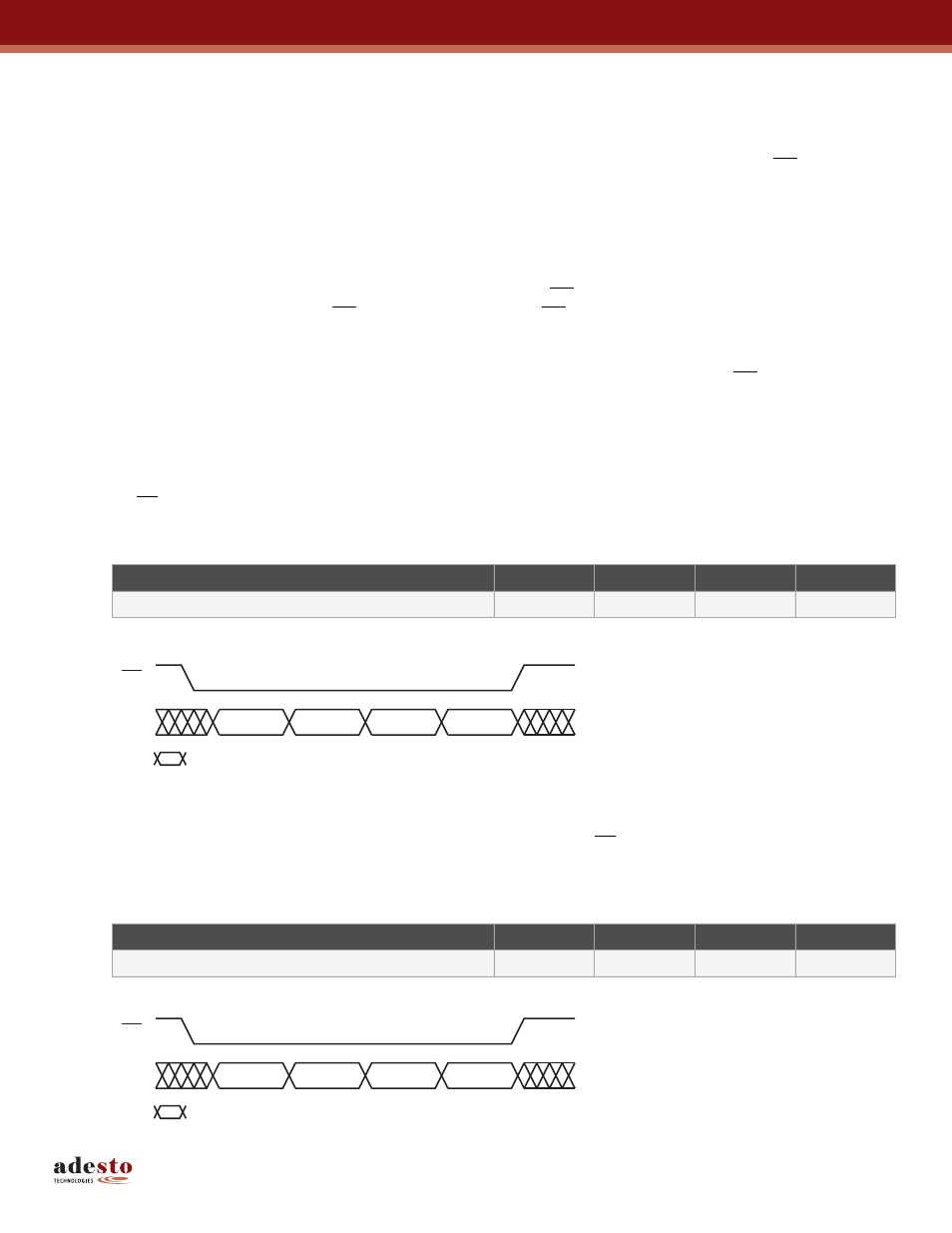
Figure 7-1. Enable Sector Protection
7.1.2
Disable Sector Protection
To disable the sector protection, a 4-byte command sequence of 3Dh, 2Ah, 7Fh, and 9Ah must be clocked into the
device. After the last bit of the opcode sequence has been clocked in, the CS pin must be deasserted to disable the
sector protection.
Table 7-2.
Disable Sector Protection Command
Figure 7-2. Disable Sector Protection
Command
Byte 1
Byte 2
Byte 3
Byte 4
Enable Sector Protection
3Dh
2Ah
7Fh
A9h
3Dh
2Ah
7Fh
9Ah
CS
Each transition represents eight bits
SI
Command
Byte 1
Byte 2
Byte 3
Byte 4
Disable Sector Protection
3Dh
2Ah
7Fh
9Ah
3Dh
2Ah
7Fh
9Ah
CS
Each transition represents eight bits
SI