Crystal oscillators, Architectural overview – Rainbow Electronics AT90C8534 User Manual
Page 4
AT90C8534
4
Crystal Oscillators
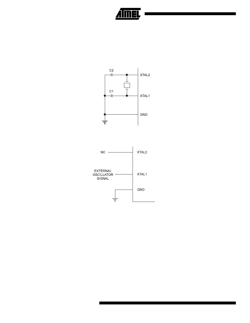
XTAL1 and XTAL2 are input and output, respectively, of an inverting amplifier that can be configured for use as an on-chip
oscillator, as shown in Figure 2. Either a quartz crystal or a ceramic resonator may be used. To drive the device from an
external clock source, XTAL2 should be left unconnected while XTAL1 is driven as shown in Figure 3. Note that XTAL2
should not be used to drive other components.
Figure 2. Oscillator Connections
Figure 3. External Clock Drive Configuration
Architectural Overview
The fast-access register file concept contains 32 x 8-bit general-purpose working registers with a single clock cycle access
time. This means that during one single clock cycle, one ALU (Arithmetic Logic Unit) operation is executed. Two operands
are output from the register file, the operation is executed and the result is stored back in the register file – in one clock
cycle.
Six of the 32 registers can be used as three 16-bit indirect address register pointers for Data Space addressing, enabling
efficient address calculations. One of the three address pointers is also used as the address pointer for the constant table
look-up function. These added function registers are the 16-bit X-register, Y-register and Z-register.
The ALU supports arithmetic and logic functions between registers or between a constant and a register. Single register
operations are also executed in the ALU. Figure 4 shows the AT90C8534 AVR RISC microcontroller architecture.
In addition to the register operation, the conventional memory addressing modes can be used on the register file as well.
This is enabled by the fact that the register file is assigned the 32 lowermost Data Space addresses ($00 - $1F), allowing
them to be accessed as though they were ordinary memory locations.