Timer counter0 – tcnt0, Bit timer/counter1, Timer/counter1 control register – tccr1 – Rainbow Electronics AT90C8534 User Manual
Page 26
AT90C8534
26
Timer Counter0 – TCNT0
The Timer/Counter0 is realized as an up-counter with read and write access. If the Timer/Counter0 is written and a clock
source is selected, the Timer/Counter0 continues counting in the timer clock cycle following the write operation.
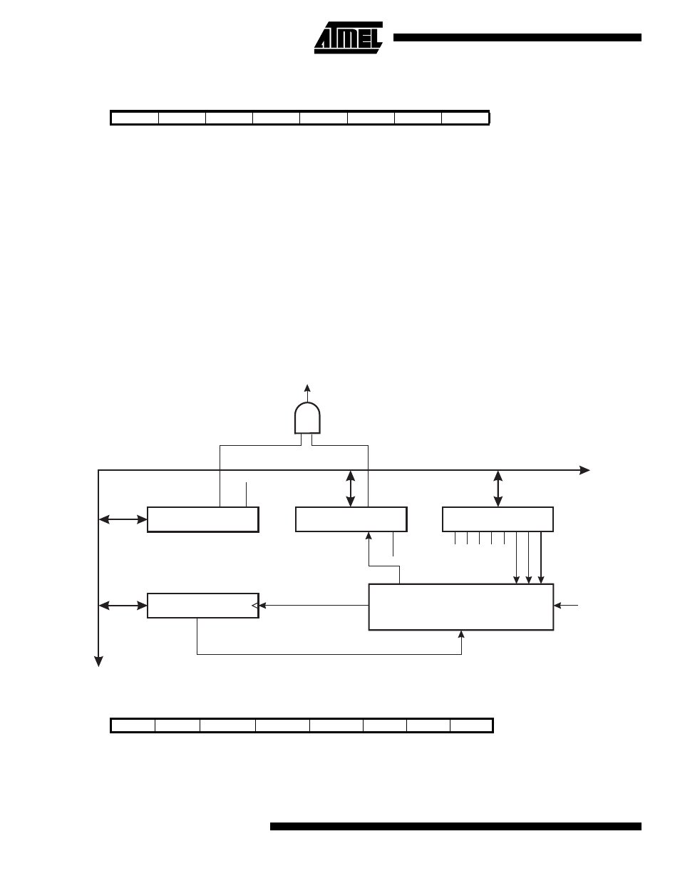
16-bit Timer/Counter1
Figure 28 shows the block diagram for Timer/Counter1.
The 16-bit Timer/Counter1 can select clock source from CK or prescaled CK. In addition, it can be stopped as described in
the specification for the Timer/Counter1 Control Register – TCCR1. The overflow status flag is found in the Timer/Counter
Interrupt Flag Register – TIFR. Control signals are found in the Timer/Counter1 Control Register – TCCR1. The interrupt
enable/disable setting for Timer/Counter1 is found in the Timer/Counter Interrupt Mask Register – TIMSK.
The 16-bit Timer/Counter1 features both a high resolution and a high accuracy usage with the lower prescaling opportuni-
ties. Similarly, the high prescaling opportunities make the Timer/Counter1 useful for lower speed functions or exact timing
functions with infrequent actions.
Figure 28. Timer/Counter1 Block Diagram
Timer/Counter1 Control Register – TCCR1
•
Bits 7..3 – Res: Reserved Bits
These bits are reserved bits in the AT90C8534 and always read zero.
Bit
7
6
5
4
3
2
1
0
$32 ($52)
MSB
LSB
TCNT0
Read/Write
R/W
R/W
R/W
R/W
R/W
R/W
R/W
R/W
Initial value
0
0
0
0
0
0
0
0
Bit
7
6
5
4
3
2
1
0
$2E ($4E)
–
–
–
–
–
CS12
CS11
CS10
TCCR1
Read/Write
R
R
R
R
R
R/W
R/W
R/W
Initial value
0
0
0
0
0
0
0
0
8-BIT DA
T
A
BUS
T/C1 CONTROL
REGISTER (TCCR1)
TIMER/COUNTER1
(TCNT1)
0
15
T/C CLK SOURCE
CONTROL
LOGIC
CS12
CS11
CS10
CK
T/C1 OVER-
FLOW IRQ
TIMER INT. MASK
REGISTER (TIMSK)
TOIE0
TOIE1
TIMER INT. FLAG
REGISTER (TIFR)
TOV0
TOV1