Adc noise canceling techniques – Rainbow Electronics AT90C8534 User Manual
Page 36
AT90C8534
36
ADC Noise Canceling Techniques
Digital circuitry inside and outside the AT90C8534 generates EMI, which might affect the accuracy of analog measure-
ments. If conversion accuracy is critical, the noise level can be reduced by applying the following techniques:
1.
The analog part of the AT90C8534 and all analog components in the application should have a separate analog
ground plane on the PCB. This ground plane is connected to the digital ground plane via a single point on the PCB.
2.
Keep analog signal paths as short as possible. Make sure analog tracks run over the analog ground plane, and
keep them well away from high-speed switching digital tracks.
3.
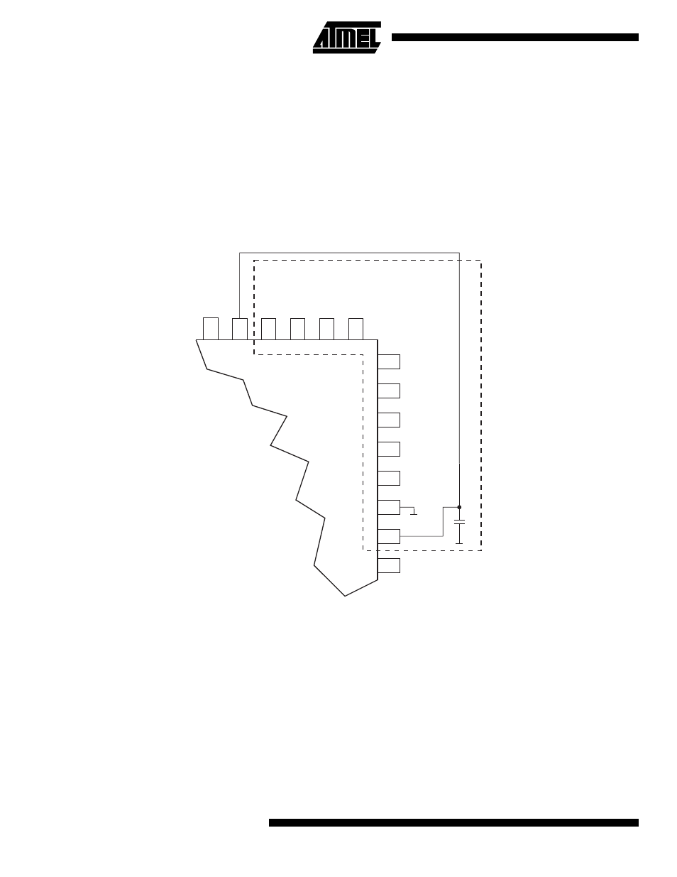
The AVCC pin on the AT90C8534 should be connected to the digital VCC supply voltage as shown in Figure 34.
4.
Use the ADC noise canceler function to reduce induced noise from the CPU.
Figure 34. ADC Power Connections
GND
VCC
ADIN0
ADIN1
ADIN2
ADIN3
AVCC
AGND
10nF
Analog Ground Plane
A
T90VC8534
ADIN4
ADIN5
NOTE: PIN PLACEMENT IS AN ILLUSTRATION ONLY