Analog-to-digital converter, Operation – Rainbow Electronics AT90C8534 User Manual
Page 30
AT90C8534
30
Analog-to-digital Converter
Feature list:
• 10-bit Resolution
• ± 2 LSB Accuracy (AVcc = 3.3 - 6.0V)
• 76 - 175
µ
s Conversion Time
• Up to 13 kSPS
• 6 Multiplexed Input Channels
• Rail-to-rail Input Range
• Free Run or Single Conversion Mode
• Interrupt on ADC Conversion Complete
• Sleep Mode Noise Canceler
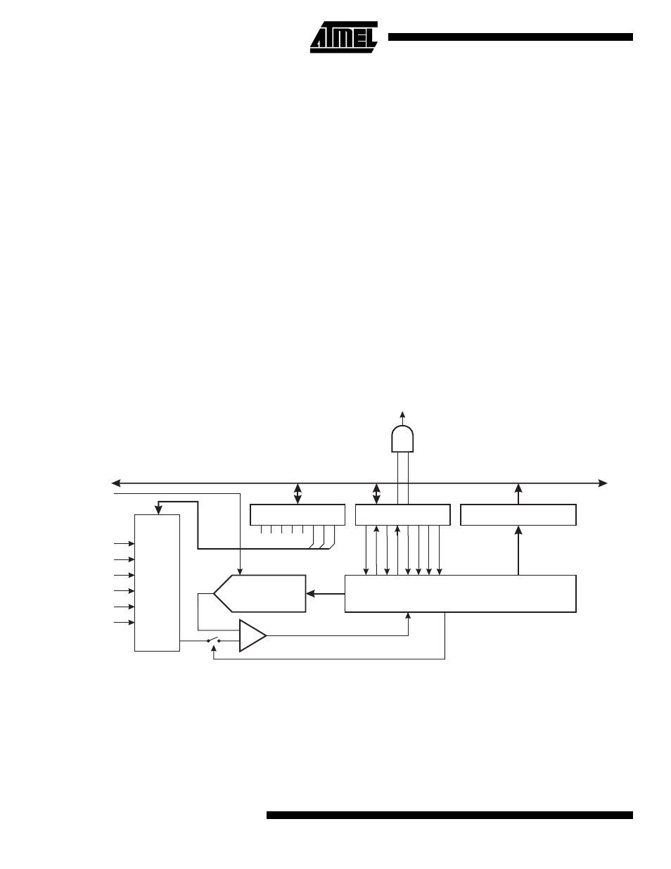
The AT90C8534 features a 10-bit successive approximation ADC. The ADC is connected to a 6-channel Analog Multi-
plexer, which allows each of the pins ADIN5..0 to be used as an input for the ADC. The ADC contains a Sample and Hold
Amplifier that ensures that the input voltage to the ADC is held at a constant level during conversion. A block diagram of the
ADC is shown in Figure 29.
The ADC has two separate analog supply voltage pins, AVCC and AGND. AGND must be connected to GND, and the
voltage on AVCC must not differ more than ± 0.3V from V
CC
. See “ADC Noise Canceling Techniques” on page 36 for how
to connect these pins.
Figure 29. Analog-to-digital Converter Block Schematic
Operation
The ADC can operate in two modes – Single Conversion and Free Run. In Single Conversion Mode, each conversion will
have to be initiated by the user. In Free Run Mode the ADC is constantly sampling and updating the ADC Data Register.
The ADFR bit in ADCSR selects between the two available modes.
The ADC is enabled by writing a logical “1” to the ADC Enable bit, ADEN in ADCSR. The first conversion that is started
after enabling the ADC will be preceded by a dummy conversion to initialize the ADC. To the user, the only difference will
be that this conversion takes 12 more ADC clock pulses than a normal conversion.
ADC CONVERSION
COMPLETE IRQ
8-BIT DATA BUS
9
0
ADC MULTIPLEXER
SELECT (ADMUX)
ADC CTRL. & STATUS
REGISTER (ADCSR)
ADC DATA REGISTER
(ADCH/ADCL)
MUX2
ADIE
ADIE
ADFR
ADBSY
ADES
ADIF
ADIF
MUX1
MUX0
ADPS0
ADPS1
ADPS2
6-
CHANNEL
MUX
CONVERSION LOGIC
10-BIT DAC
+
-
SAMPLE & HOLD
COMPARATOR
Analog
Inputs
External
Reference
Voltage