Reset, External reset – Rainbow Electronics AT90C8534 User Manual
Page 19
AT90C8534
19
Reset
During reset, all I/O registers are set to their initial values and the program counter is set to address $000. When reset is
released, the program starts execution from this address. The instruction placed in address $000 must be an RJMP (rela-
tive jump) instruction to the reset handling routine. If the program never enables an interrupt source, the interrupt vectors
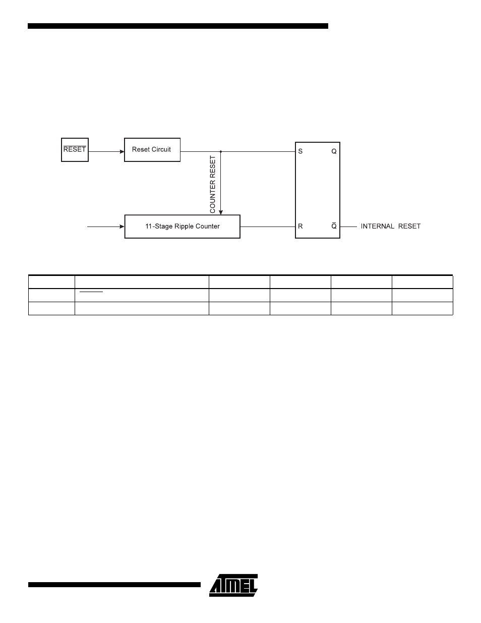
are not used and regular program code can be placed at these locations. The circuit diagram in Figure 23 shows the reset
logic. Table 3 defines the timing and electrical parameters of the reset circuitry
Figure 23. Reset Logic
External reset
The AT90C8534 has one source of reset: the external reset pin. The external reset is used for three purposes:
1.
Power-on Reset. During power-on, the external reset must be held active (low) until 100 ns after V
CC
has reached
the minimum operation voltage.
2.
Brown-out Reset. If V
CC
drops below the minimum operation voltage during operation, the external reset must go
active immediately, and must be held active until 100 ns after V
CC
rises to the minimum operation voltage.
3.
Normal Operation Reset. During normal operation, reset is generated by holding the external reset active for at
least 100 ns.
When the external reset is released, an internal timer that is clocked from the external clock input is started, holding the
internal reset active until the external clock source has toggled a certain number of times (see Table 3). This is illustrated in
Figure 24 and Figure 25.
Table 3. Reset Characteristics (V
CC
= 5.0V)
Symbol
Parameter
Min
Typ
Max
Units
V
RST
RESET Pin Threshold Voltage
0.6 V
CC
V
t
TOUT
Reset Delay Time-out Period
-
1026
-
clocks
CLOCK