Rainbow Electronics TS81102G0 User Manual
Page 7
7
TS81102G0
2105C–BDC–11/03
Counter
Programmable
State
When the counter is reset, its initial states depends on the conversion ratio:
•
1:8: counting on 8 bits,
•
1:4: counting on 4 bits.
Pipeline Delay
The maximum pipeline delay depends on the conversion ratio:
•
1:8: pipeline delay = 7
•
1:4: pipeline delay = 3
8-/10-bit, with NAP
Mode for the 2
Unused Bit
The DMUX is a 10-bit parallel device. The last two bits (bits 8 and 9) may not be used, and the
corresponding functions are set to nap mode to reduce power consumption.
ECL Differential
Input Data
Input data are ECL compatible (Voh = -0.8V, Vol = -1.8V).
The minimum swing required is 100 mV differential.
All inputs have a 100
Ω
differential termination resistor. The middle point of these resistors is
connected to ground through a 10 pF capacitor.
Figure 7.
ECL Differential Input Data
50
Ω Differential
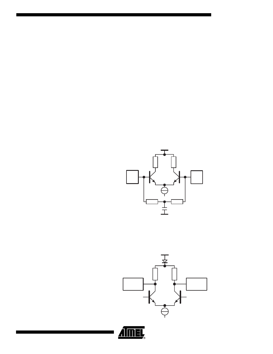
Output Data
The output clock for the ADC is generated through a 50
Ω
loaded long tailed. The 50
Ω
resistor
is connected to the ground pad via a diode. The levels are (on the 100
Ω
differential termina-
tion resistor): Vol = -1.4V, Voh = -1.0V.
Figure 8.
50
Ω
Differential Output Data
ClkIn
ClkInb
Gnd
10 pF
50
Ω
50
Ω
50
Ω
50
Ω
ADCDelAdjOut
Gnd
ADCDelAdjOutb