Rainbow Electronics TS81102G0 User Manual
Page 29
29
TS81102G0
2105C–BDC–11/03
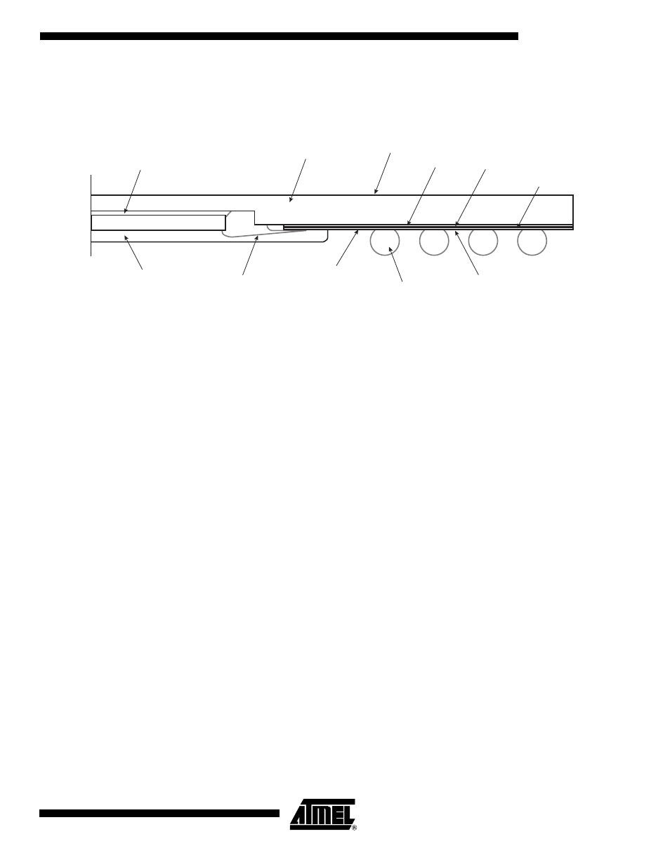
Detailled Cross
Section
The following diagram depicts a detailed cross section of the DMUX TBGA package.
Figure 24.
TBGA 240: 1/2 Cross Section
In the DMUX package shown above, the die’s rear side is attached to the copper heat
spreader, so the copper heat spreader is at -5V.
It is necessary to use a heat sink tied to the copper heat speader.
Moreover, there is only a little layer of painting over the copper heat spreader which does not
isolate it.
It is therefore recommended to either isolate the heat sink from the other components of the
board or to electrically isolate the copper heat spreader from the heat sink. In the latter case,
one should use adequate low Rth electrical isolation.
Die Attach Epoxy/Ag
Block Epoxy resin
encapsulant
Gold
wires
Silicon Die
Solder Mask
Metal 1 side
Solder Mask
Metal 2 side
Adhesive
Block overcoat
Polyimide Tape
Sn/Pb/Ag
62/36/2 Eutectic
Solder Balls
Copper traces
and
Solder Balls Pads
on metal 1 side
Copper Heatspreader