Rainbow Electronics TS81102G0 User Manual
Page 12
12
TS81102G0
2105C–BDC–11/03
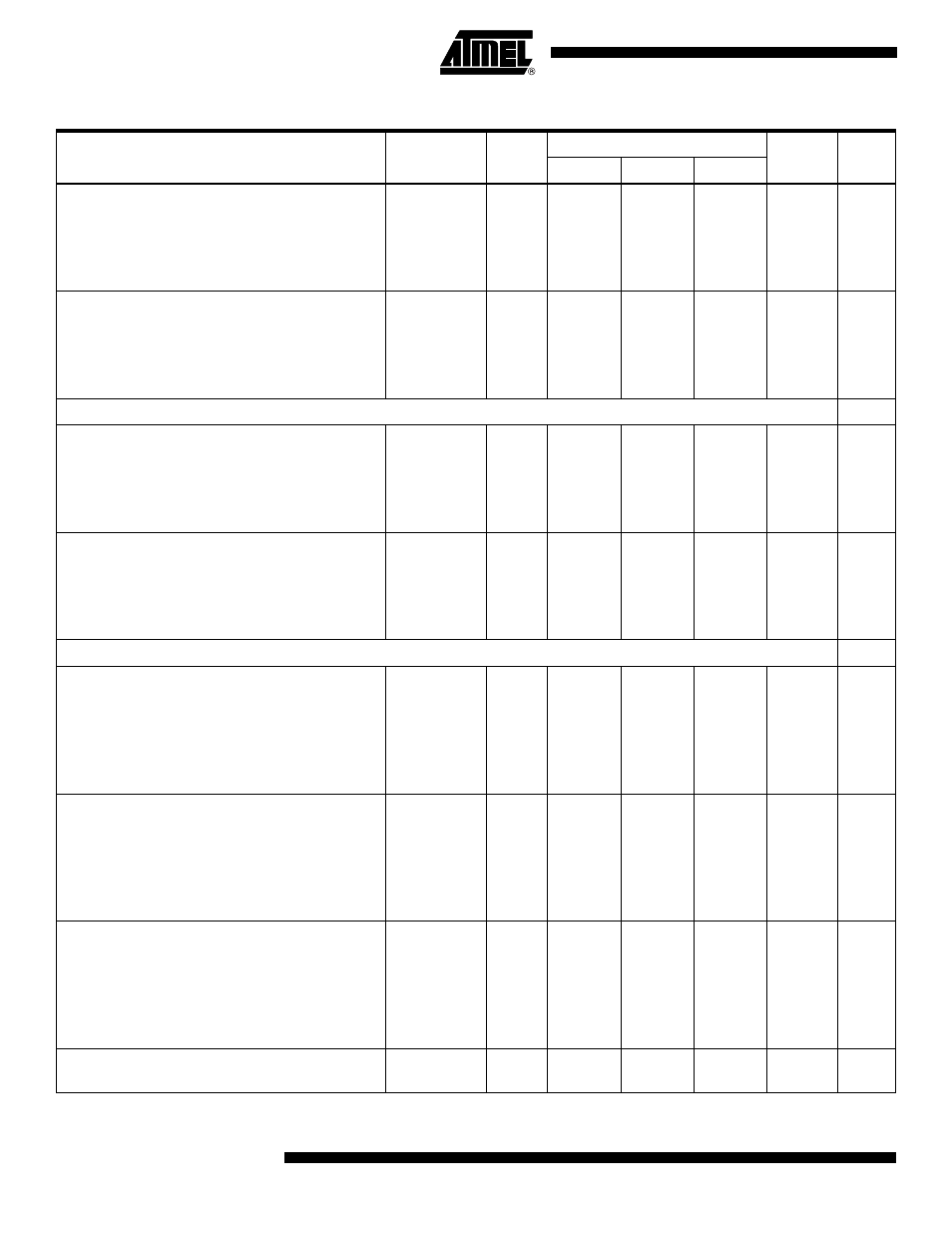
PECL (50
Ω
)
1:8, 8 bits
1:8, 10 bits
1:4, 8 bits
1:4, 10 bits
PD
PD
PD
PD
1
5.8
6.6
4.2
4.6
6.2
7.1
4.4
4.8
6.6
7.6
4.6
5.1
W
W
W
W
TTL (75
Ω
)
1:8, 8 bits
1:8, 10 bits
1:4, 8 bits
1:4, 10 bits
PD
PD
PD
PD
1
6.8
7.8
4.7
5.2
7.3
8.4
4.9
5.5
7.7
9
5.1
5.8
W
W
W
W
Delay Adjust Control
DMUXDelAdjCtrl differential voltage
250 ps
500 ps
750 ps
Input current
DDAC
IDDAC
–
–
–
–
–
–
–
-0.5
0
0.5
–
–
–
–
–
–
V
V
V
mA
ADCDelAdjCtrl differential voltage
250 ps
500 ps
750 ps
Input current
ADAC
IADAC
–
–
–
–
–
–
–
-0.5
0
0.5
–
–
–
–
–
–
V
V
V
mA
Digital Outputs
ECL Output
(assuming V
PLUSD
= 0V, SWIADJ = 0V, 50
Ω
termination resistor on board)
Logic “0” voltage
Logic “1” voltage
Reference voltage
V
OL
V
OH
V
REF
1
–
–
–
-2.12
-1.16
-1.40
–
–
–
V
V
V
PECL Output
(assuming V
PLUSD
= 3.3V, SWIADJ = 0V, 50
Ω
termination resistor on board)
Logic “0” voltage
Logic “1” voltage
Reference voltage
V
OL
V
OH
V
REF
1
–
–
–
1.27
2.44
1.83
–
–
–
V
V
V
TTL Output
(assuming V
PLUSD
= 3.3V, SWIADJ = 0V, 75
Ω
termination resistor on board)
Logic “0” voltage
Logic “1” voltage
Reference voltage
V
OL
V
OH
V
REF
1
–
–
–
0.9
2.31
1.2
–
–
–
V
V
V
Output level drift with temperature (data and DR
outputs)
–
–
–
-1.3
–
mV/
°
C
Table 4.
Electrical Specifications (Continued)
Parameter
Symbol
Test
Level
Value
Unit
Note
Min
Typ
Max